Eureka AIR delivers breakthrough ideas for toughest innovation challenges, trusted by R&D personnel around the world.

Digital direction display for a trolling motor

a digital direction display and trolling motor technology, applied in the direction of navigational aid arrangements, speed/acceleration/shock instrument details, propulsive elements, etc., can solve the problem of complex mechanical linkages

Active Publication Date: 2021-02-02
NAVICO HLDG
View PDF16 Cites 0 Cited by
  • Summary
  • Abstract
  • Description
  • Claims
  • Application Information

AI Technical Summary

Benefits of technology

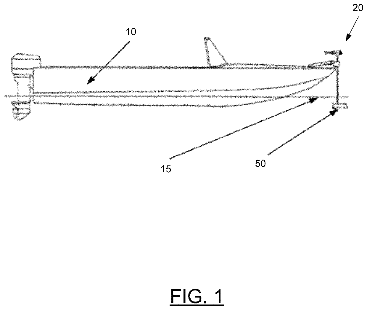
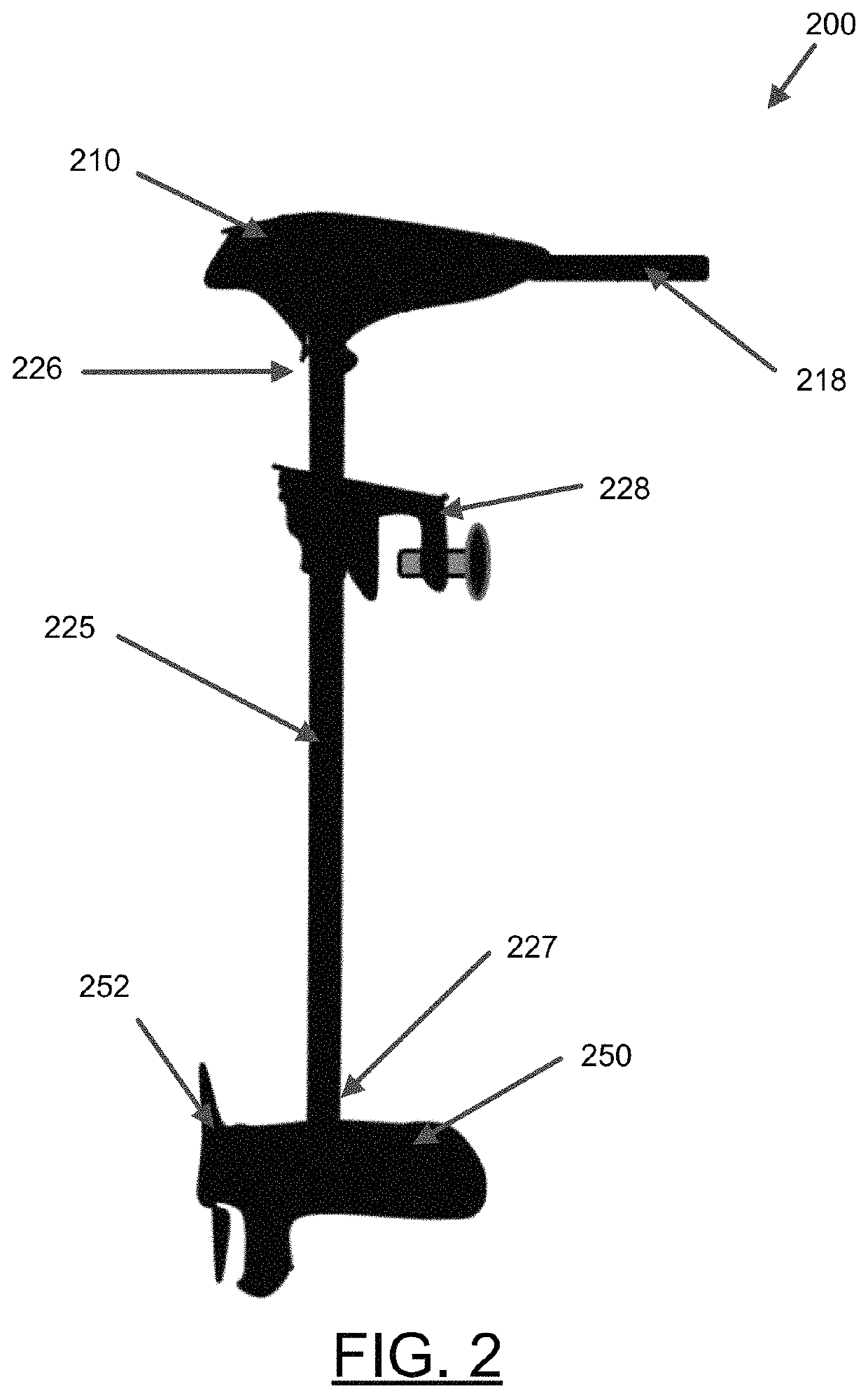
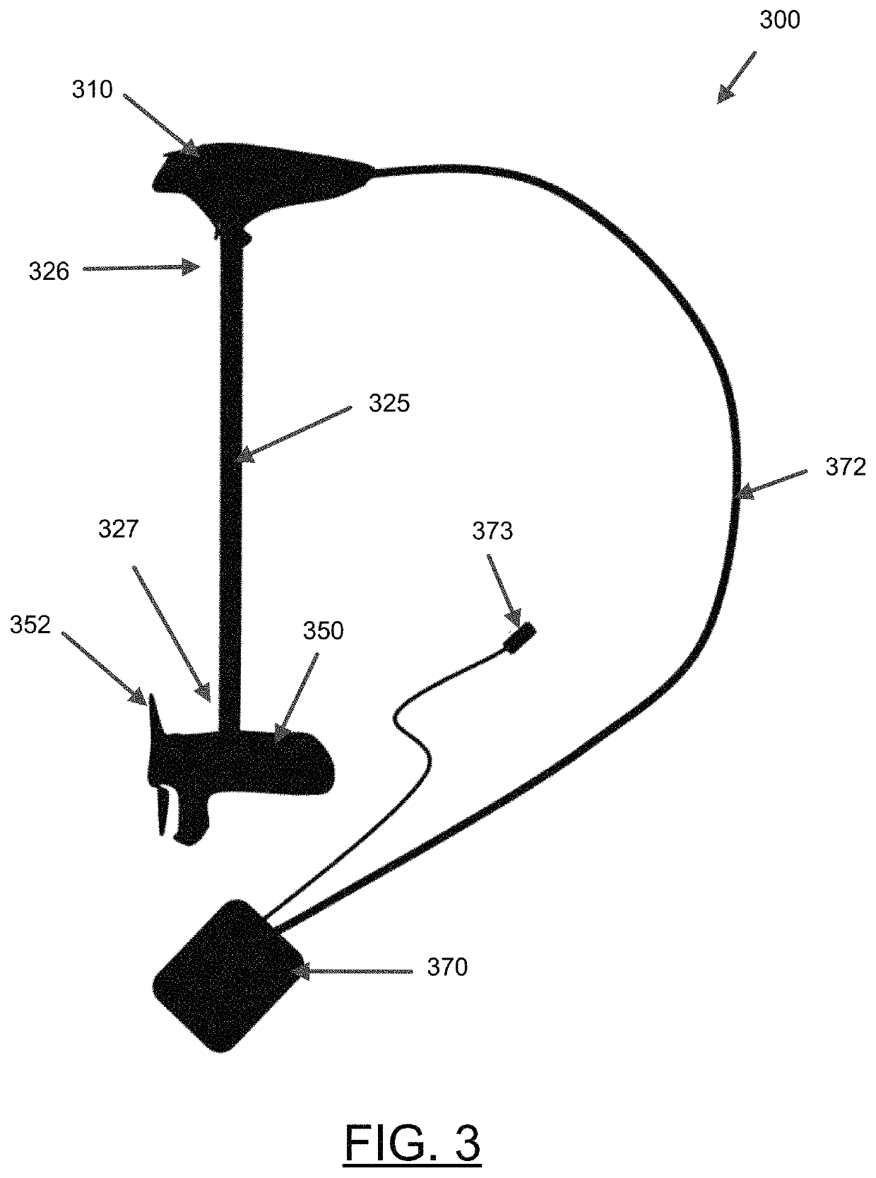
[0005]In some example embodiments, a trolling motor is provided including a position sensor configured to determine the direction of the trolling motor relative to the watercraft. The trolling motor also includes a digital display configured to display the direction of the trolling motor. The position sensor and digital display may enable a less complicated solution that can be more easily water proofed. Additionally, the digital display may be utilized to provide additional information about the trolling motor to the user.
[0007]In some embodiments, certain features / components of the trolling motor may be powered from one or more batteries of the watercraft or trolling motor. In some example embodiments, the trolling motor may include a battery sensor configured to measure the remaining charge on such batteries. For example, the battery sensor may measure a battery voltage or battery current. The digital display may indicate a remaining charge on the battery, such as a low charge warning light, a charge bar, or charge percentage. The indication of the remaining charge on the battery may be beneficial for preventing the battery charge to completely run out or limiting running of the trolling motor when the battery charge is low.

Problems solved by technology

These mechanical linkages may be quite complex, including numerous mechanical components that are difficult to waterproof and subject to mechanical failure or drift.

Method used


Image

  • Digital direction display for a trolling motor
  • Digital direction display for a trolling motor
  • Digital direction display for a trolling motor

Examples


Embodiment Construction

[0051]Exemplary embodiments of the present invention now will be described more fully hereinafter with reference to the accompanying drawings, in which some, but not all embodiments of the invention are shown. Indeed, the invention may be embodied in many different forms and should not be construed as limited to the exemplary embodiments set forth herein; rather, these embodiments are provided so that this disclosure will satisfy applicable legal requirements. Like reference numerals refer to like elements throughout.

[0052]Some embodiments of the present invention provide trolling motor assemblies with a position sensor and digital display. Such example embodiments enable an indication of the direction of the trolling motor without complicated mechanical linkages, which may be subject to failure or may be difficult to waterproof. Additionally, the digital display may be used to provide other information relevant to the trolling motor, such as speed, motor output, battery charge, ope...


PUM


Abstract

A trolling motor is provided including a position sensor configured to determine the direction of the trolling motor housing, a digital display, a processor, and a memory including computer program code. The computer program code is configured to, when executed, cause the processor to receive position data from the position sensor, generate display data based on the position data, and cause the display data to be displayed on the digital display. The digital display is integrated with the main housing and configured to display the display data so as to provide an indication of the current direction of the trolling motor housing relative to the watercraft.

Description

CROSS-REFERENCE TO RELATED APPLICATIONS[0001]This application claims priority to and is a continuation of U.S. non-provisional patent application Ser. No. 16 / 276,057, entitled “Digital Direction Display for a Trolling Motor,” filed Feb. 14, 2019, which is incorporated by reference herein in its entirety.FIELD OF THE INVENTION[0002]Embodiments of the present invention relate generally to trolling motor assemblies and, more particularly, to systems, assemblies, and associated methods for providing a trolling motor assembly with a digital direction display.BACKGROUND OF THE INVENTION[0003]Trolling motors are often used during fishing or other marine activities. The trolling motors attach to the watercraft and propel the watercraft along a body of water. For example, trolling motors may provide secondary propulsion or precision maneuvering that can be ideal for fishing activities. The trolling motors, however, may also be utilized for the main propulsion system of watercraft. Applicant ...

Claims


Application Information

Patent Timeline
Patent Type & Authority Patents(United States)
IPC IPC(8): B63H20/00B63B49/00G01C21/20G01P1/07G01P5/00
CPCB63B49/00B63H20/007G01C21/203G01P1/07G01P5/00B63H2025/045
Inventor BAILEY, PAUL ROBERT
Owner NAVICO HLDG
Why Eureka
Eureka Blog
Learn More