Eureka AIR delivers breakthrough ideas for toughest innovation challenges, trusted by R&D personnel around the world.

Wiring member connection structure

a wiring member and connection structure technology, applied in the direction of electrical apparatus casings/cabinets/drawers, coupling device connections, casings/cabinets/drawers details, etc., can solve the problem and achieve the effect of easy lowering of the reliability of the electric connection of the mainline wiring member parts

Active Publication Date: 2019-09-24
YAZAKI CORP
View PDF10 Cites 0 Cited by
  • Summary
  • Abstract
  • Description
  • Claims
  • Application Information

AI Technical Summary

Benefits of technology

[0007]However, in the aforementioned wire member connection structure, the cut two mainline wiring member parts are electrically connected through the power supply distribution box. For this reason, there may arise a problem that the number of connection places is so large that reliability about the electric connection of the mainline wiring member parts is easily lowered.
[0011]According to the wiring member connection structure having the aforementioned configuration (1), the bolt is erect and bonded perpendicularly to the conductor flat surface of the flat conductor exposed at the intermediate position of the belt-like flat wiring member where the coating has been removed. The circuit board is fastened to the bolt that has penetrated the casing bottom wall of the casing covering the circuit board. The connector conductively connected to the bolt is provided on the circuit board, and the connector fitting portion of the connector is exposed to the outside from the casing. A counterpart connector provided on a terminal of another wiring member is fitted to the connector fitting portion exposed from the casing. That is, the other wiring member can be electrically connected to the intermediate position of the flat wiring member in a state in which the flat wiring member is not cut but is continuous over an entire area in a longitudinal direction. The other wiring member is connected to the flat wiring member without dividing the flat wiring member. Accordingly, the number of connection places can be reduced. As a result, the wiring member connection structure having the present configuration can have higher electric connection reliability between the flat wiring member and the other wiring member than the background-art wiring member connection structure in which the two cut mainline wiring member parts are electrically connected through the electric power distribution box.
[0013]According to the wiring member connection structure having the aforementioned configuration (2), the flat wiring members are laminated to each other to form a laminated wiring body in which a plurality of circuits are laminated. In such a lamination structure, the upper flat wiring member is superimposed on the lower flat wiring member. For this reason, conductive connection to another wiring member in an upper surface of the intermediate position of the lower flat wiring member in an extension direction thereof is usually difficult. To solve this problem, the wiring member connection structure having the present configuration is provided with the extraction portion. The extraction portion has a function to prevent the upper flat wiring member from standing in the way of conducive connection to the bolt provided on the upper surface of the lower flat wiring member. Thus, conductive connection to the flat wiring members in the respective layers of the laminated wiring body can be performed at desirable intermediate positions of the laminated wiring body in the extension direction. As a result, the laminated wiring body routed in a vehicle can be used to make it easy to connect a power supply etc. to accessories at a short distance. The accessories are mounted at desirable positions of the vehicle. That is, the flat wiring members can be electrically connected to other wiring members in a state in which the flat wiring members are not cut but extend continuously over the entire area in the longitudinal direction. In other words, the degree of freedom for selecting connection positions of the other wiring members is improved.
[0015]According to the wiring member connection structure having the aforementioned configuration (3), the bypass portion is formed in the at least one flat wiring member. The bypass portion serves as the extraction portion where the at least one flat wiring member is bent in the width direction thereof to prevent the flat wiring members from being superimposed on each other. When the flat wiring members are superimposed on each other, the bolt erectly provided on the bypass portion of the flat wiring member is not superimposed on the other flat wiring member. Thus, bolts can be disposed on an upper surface of the laminated wiring body so as to be arranged side by side in the width direction crossing the extension direction of the laminated wiring body. The circuit board can be fastened and fixed to the bolts. According to the wiring member connection structure, the pair of bolts that are, for example, connected to a positive electrode and a negative electrode can be provided on the laminated wiring body relatively narrow in width, and side by side in the width direction of the laminated wiring body. In addition, an insertion hole of the lower flat wiring member through which the bolt is inserted does not have to be bored in the upper flat wiring member. Accordingly, a decrease of a sectional area in the upper flat wiring member can be suppressed.
[0019]According to the wiring member connection structure having the aforementioned configuration (5), the annular packing is mounted on the outer circumference of the bolt, and the circuit board is fastened and fixed to the bolt to squash the annular packing. Thus, a connection portion between the flat wiring member and the casing can be easily made waterproof.
[0020]According to the wiring member connection structure according to the present invention, it is possible to connect another wiring member to an intermediate position of each wiring member with high connection reliability.

Problems solved by technology

For this reason, there may arise a problem that the number of connection places is so large that reliability about the electric connection of the mainline wiring member parts is easily lowered.

Method used


Image

  • Wiring member connection structure
  • Wiring member connection structure
  • Wiring member connection structure

Examples


Embodiment Construction

[0027]An embodiment according to the present invention will be described below with reference to the drawings.

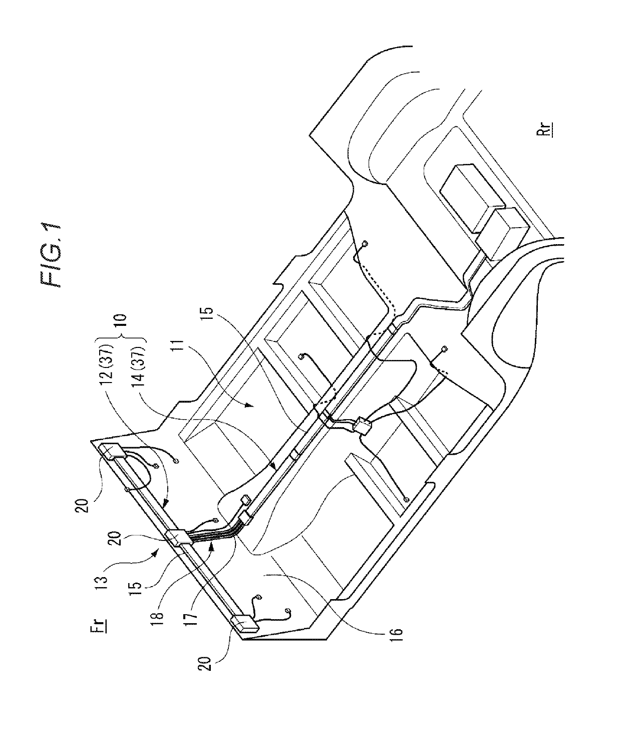
[0028]A wiring member connection structure according to the present embodiment provides a connection structure that is excellent in connection reliability and water sealing performance in a backbone wire harness expected as a future wire harness routing form (in a form in which a power supply distribution box is connected to an intermediate portion of a battery cable, and power is distributed from the power supply distribution box).

[0029]FIG. 1 is a perspective view showing an underbody 11 mounted with a wiring member connection portion 13 connected by the wiring member connection structure according to the embodiment of the present invention. In the underbody 11 serving as a body panel, a front of the vehicle is denoted as Fr, and a rear of the vehicle is denoted as Rr in accordance with a direction viewed from a driver.

[0030]As shown in FIG. 1, a vehicle circuit body 10 ac...


PUM


Abstract

A wiring member connection structure is provided. The wiring member connection structure includes: a flat wiring member formed by covering an outer circumference of a belt-like flat conductor with an insulating coating; a bolt which is erect and bonded perpendicularly to a conductor flat surface of the flat conductor exposed at an intermediate position of the flat wiring member where the coating is removed; a circuit board that has a connector conductively connected to the bolt through a circuit conductor and that is fastened and fixed to the bolt penetrating the circuit board; and a casing that has a casing bottom wall including a bolt insertion hole through which the bolt is inserted to penetrate the circuit board, and that covers the circuit board so as to expose a connector fitting portion of the connector to the outside.

Description

CROSS-REFERENCE TO RELATED APPLICATIONS[0001]This application is based on and claims priority under 35 USC 119 from Japanese Patent Application No. 2017-234510 filed on Dec. 6, 2017, the contents of which are incorporated herein by reference.TECHNICAL FIELD[0002]The present invention relates to a wiring member connection structure.BACKGROUND ART[0003]In the background art, there has been known a wiring member connection structure in which a long mainline wiring member and a branch wiring member are electrically connected. The long mainline wiring member is routed in a vehicle to be able to transmit electric power. The branch wiring member is routed in the vehicle to be able to transmit electric power, and branches off from the mainline wiring member. As such a connection structure, the following connection structure will be shown by way of example. In a vehicle mounted with a battery on a rear side thereof, assume that a long mainline wiring member is routed in a front / rear directio...

Claims


Application Information

Patent Timeline
Patent Type & Authority Patents(United States)
IPC IPC(8): H01R12/00H01R12/58H02G3/36H05K5/00H05K1/11H05K5/06H05K5/02B60R16/033H02G3/08H01R12/72B60R16/02
CPCH05K5/0069H02G3/36H05K5/069H05K5/006H01R12/58H05K1/115H05K5/0247H05K5/0073H01R2201/26H01R12/722B60R16/033B60R16/0207H05K5/0056H02G3/088B60R16/0215H01R4/34H01R13/447H01R13/521H05K1/0263H05K2201/10409H05K2201/10272
Inventor KATO, SHINGO
Owner YAZAKI CORP
Why Eureka
Eureka Blog
Learn More