Two stage compact evaporator for vehicle waste heat recovery system

a technology of vehicle waste heat recovery and compact evaporator, which is applied in the operation mode of machines, machines/engines, lighting and heating apparatus, etc., can solve the problems of considerable heat generation, achieve better working temperature, improve heat retention, and improve the effect of heat retention

Active Publication Date: 2021-02-09
VOLVO CAR CORP
View PDF17 Cites 2 Cited by
  • Summary
  • Abstract
  • Description
  • Claims
  • Application Information

AI Technical Summary

Benefits of technology

[0006]In view of above-mentioned and other drawbacks of the prior art, it is an object of the present invention to provide an improved WHR ORC system. Such an improved system would include a compact two-stage evaporator including a state separator, or at least a state separator function, between the respective first and second evaporators. By using such a compact evaporator, a WHR ORC system can make better use of a water / organic blend working fluid. The organic component of the working fluid provides rapid start-up to a working vapor phase and retains the benefits of enhanced freeze prevention. The water component retains the advantages of water-based vapor having a higher working temp and being a more robust retainer of heat. The evaporator includes controlled processing of a state separator function between the respective first and second stage evaporators to prevent fluid droplets from entering the second evaporator and downstream expander especially during the start-up phase of the WHR system.
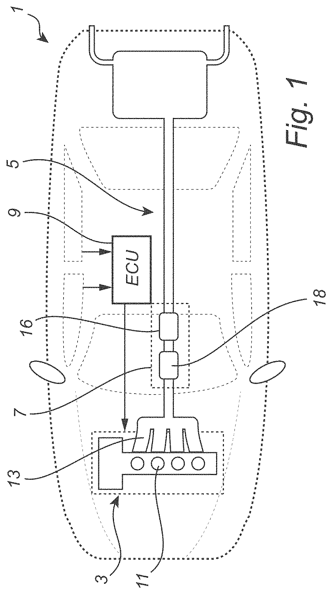
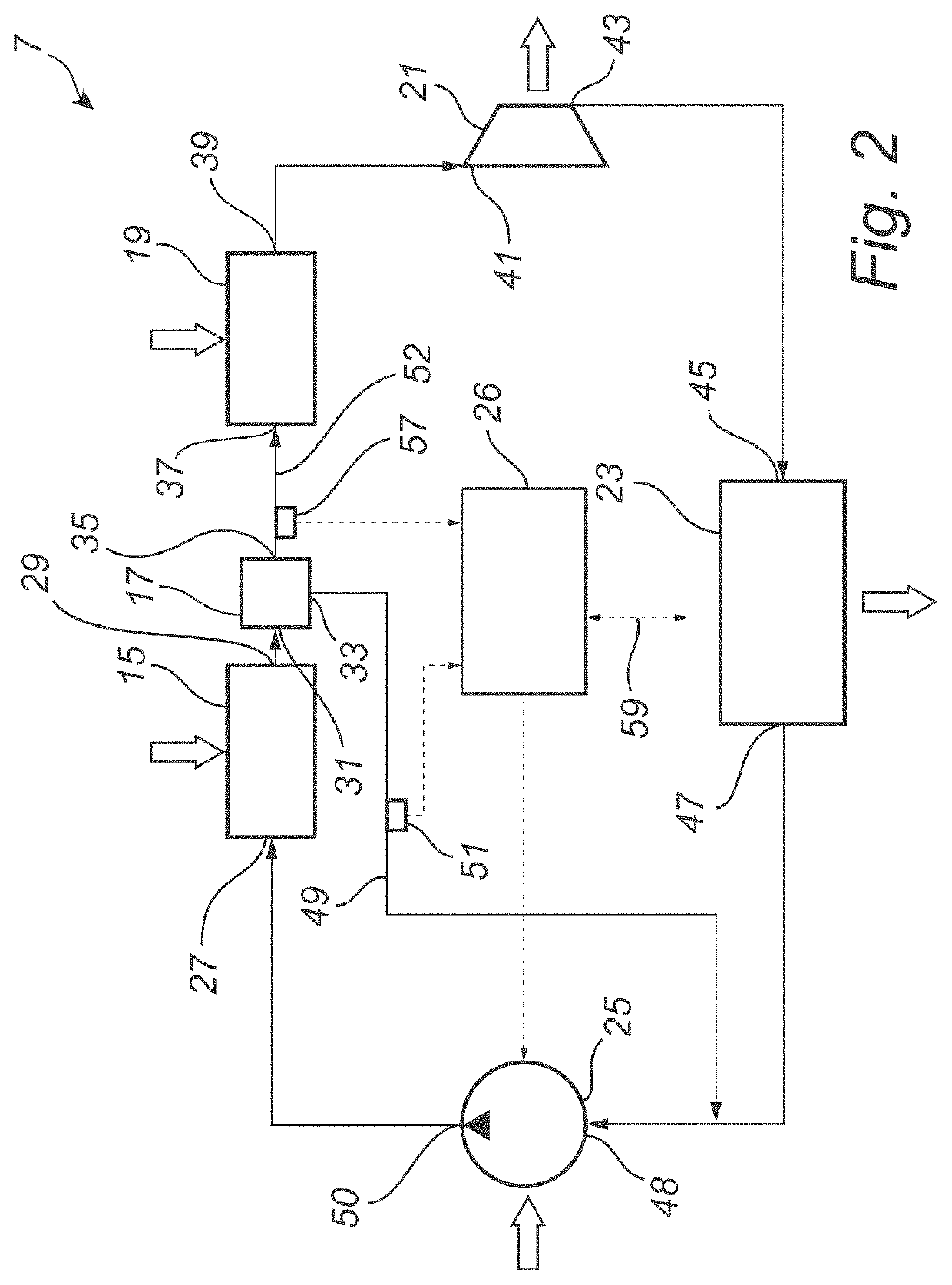
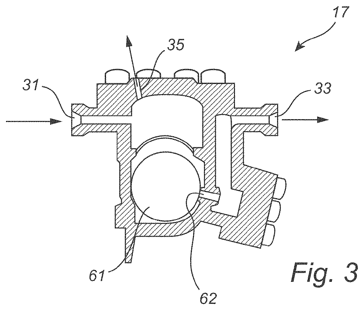
[0007]According to the present invention, it is therefore provided an enhanced waste heat recovery system for a vehicle, for converting thermal energy generated in the vehicle to mechanical energy for assisting more efficient operation of the vehicle. The WHR system includes a compact two-stage evaporator, having: 1) a first evaporator, for evaporating liquid state working fluid to a saturated vapor state working fluid through supply of heat from a first vehicle heat source; 2) a state separator, or a controlled state separator function, for separating vapor state working fluid and liquid state working fluid; and, 3) a second evaporator, connected to the vapor outlet of the state separator, for superheating vapor state working fluid through supply of additional heat from a second vehicle heat source.
[0011]The present invention is premised upon the realization that a more energy efficient conversion in a WHR blended ORC system is made possible by arranging a state separator device / function between a compact first evaporator and a second evaporator in such a way that only vapor phase working fluid enters the second evaporator, while liquid phase working fluid, thus separated, is fed back into the first evaporator and by-passes the expander. Through this configuration, the desired superheated vapor working fluid for the expander can be formed with addition of less heat than if a mix of vapor phase and liquid phase working fluid entered the second expander. The waste heat recovery system according to embodiments of the present invention can function most efficiently with a working fluid that is a mix of a first working fluid with a first boiling temperature and a second working fluid with a second boiling point, different from the first boiling point. Through a suitable selection of first and second (or more) working fluids, the waste heat recovery system can be made to function at lower temperatures, which may be beneficial in many applications, in particular vehicle applications. For instance, where a mix of water and ethanol may be used as the working fluid. Furthermore, the provision of the state separator allows feedback control of the waste heat recovery system to achieve more efficient transfer of heat to the working fluid in the first evaporator
[0012]According to various embodiments, the first outlet of the state separator may be fluid flow connected to the inlet of the first evaporator via a / the system pump. In other words, the waste heat recovery system may include a fluid conduit from the first outlet of the state separator to the conduit connecting the condenser and the pump. In these embodiments, the pump assists in maintaining a feedback flow of liquid state working fluid from the first outlet of the state separator to the inlet of the first evaporator. Alternatively, or in combination, an additional pump may be provided along the return conduit connected to the first outlet of the state separator.
[0014]Advantageously, the waste heat recovery system may further comprise a sensor for providing a signal indicative of mass flow of liquid state working fluid from the first outlet of the state separator to the inlet of the first evaporator. The control circuitry may be electrically connected to the sensor and to the pump, and configured to: acquire, from the sensor, the signal indicative of mass flow of liquid state working fluid from the first outlet of the state separator to the inlet of the first evaporator; and control the pump to supply a sufficient mass flow of liquid state working fluid to the inlet of the first evaporator to make mass flow of liquid state working fluid from the first outlet of the state separator to the inlet of the first evaporator greater than zero. Accordingly, it may be sufficient that the above-mentioned sensor provides a signal indicative of the presence of mass flow of liquid state working fluid. To facilitate control of the pump, it may however be advantageous if the above-mentioned sensor is configured to provide a signal indicative of a magnitude of the mass flow.
[0015]Using feedback control of the pump to maintain mass flow of liquid phase working fluid from the first outlet of the state separator, efficient heat transfer in the first evaporator can be provided for. In particular, the working fluid can be maintained in its saturated state in the first evaporator, before a steam film can be created on the first evaporator surface and act as insulation, reducing the heat flux from the first vehicle heat source to the working fluid in the first evaporator.

Problems solved by technology

When internal combustion engines (ICEs) are in operation, considerable heat is generated.

Method used


Image

  • Two stage compact evaporator for vehicle waste heat recovery system
  • Two stage compact evaporator for vehicle waste heat recovery system
  • Two stage compact evaporator for vehicle waste heat recovery system

Examples


Embodiment Construction

[0035]Reference will now be made in detail to exemplary embodiments and methods of the invention as illustrated in the accompanying drawings, in which like reference characters designate like or corresponding parts throughout the drawings. It should be noted, however, that the invention in its broader aspects is not limited to the specific details, representative devices and methods, and illustrative examples shown and described in connection with the exemplary embodiments and methods.

[0036]This description of exemplary embodiments is intended to be read in connection with the accompanying drawings, which are to be considered part of the entire written description. In the description, relative terms such as “horizontal,”“vertical,”“front,”“rear,”“left,”“right,”“upper,”“lower,”“top,” and “bottom” as well as derivatives thereof (e.g., “horizontally,”“downwardly,”“upwardly,” etc.) should be construed to refer to the orientation as then described or as shown in the drawing figure under ...


PUM


Abstract

A compact two-stage evaporator waste heat recovery (WHR) device (7) is disclosed, and a system using the device. The device recovers energy from waste heat passing through the device and transfers that energy to a Rankine Cycle working fluid also passing through the device. The device includes a first and second evaporator (15); and, a state separator (17) connected between the outlet of the first evaporator and the inlet of the second evaporator. The state separator (17) separates the working fluid into liquid and vapor. The liquid is re-cycled to the inlet of the first evaporator (15); the vapor is sent to the inlet of the second evaporator (19) for superheating. An overall WHR system using the device further includes an expander (21), condenser (23), and pump (25). The system further includes control circuitry (26) for controlling operation of the waste heat recovery device (7) itself and the WHR system.

Description

RELATED CASES[0001]The present claims the benefit of U.S. Provisional application Ser. 62 / 755,734, filed Nov. 5, 2018, which is incorporated herein by reference.TECHNICAL FIELD[0002]The present invention relates to a two-stage compact evaporator for installation in a waste heat recovery system for a vehicle, and to a vehicle including such a waste heat recovery system.BACKGROUND OF THE INVENTION[0003]When internal combustion engines (ICEs) are in operation, considerable heat is generated. Vehicles using ICEs discharge heat energy into the external environment through, for example, exhaust gas, engine cooling systems, charge air cooling systems. The discharged heat energy that is not used to perform useful work is typically known as “waste heat”. Waste heat recovery (WHR) systems capture a portion of the waste heat to perform useful work, such as generating electrical energy via an expander (e g., a turbine) coupled to a generator. Some WHR systems use a Rankine cycle (RC). The RC is...

Claims


Application Information

Patent Timeline
Patent Type & Authority Patents(United States)
IPC IPC(8): F02G5/02F25B5/04F25B27/02F25B39/02F25B43/00
CPCF02G5/02F25B5/04F25B27/02F25B39/02F25B43/00F01K15/02
Inventor ROLANDSON, OLA
Owner VOLVO CAR CORP
Why Eureka
Try Eureka