
Clutch system

a technology of clutches and clutches, which is applied in the direction of magnetically actuated clutches, mechanical equipment, transportation and packaging, etc., can solve the problems of friction engagement between the magnetic clutch and the torque-introducing element, and the rotational speed difference at the magnetic clutch arises, so as to achieve the effect of smooth rotational speed difference at the magnetic clutch

Active Publication Date: 2021-02-09
SCHAEFFLER TECH AG & CO KG
View PDF17 Cites 1 Cited by
  • Summary
  • Abstract
  • Description
  • Claims
  • Application Information

AI Technical Summary

Benefits of technology

[0005]In regular traction operation, a torque flow can take place from the torque-introducing element to the torque-discharging element substantially via the friction clutch. As a result, a torque produced in a motor vehicle engine designed as an internal combustion engine can be transmitted to a transmission input shaft of a motor vehicle transmission in order to drive the motor vehicle. It is also possible to connect an electric machine via an output part of the friction clutch or the torque-discharging element, and therefore, in a booster mode, the motor vehicle can be additionally driven by the electric machine operated in motor mode. For purely electrical operation of the motor vehicle, with the internal combustion engine switched off, the friction clutch can be opened by virtue of the magnetic clutch which acts as pilot clutch being opened by electrical energization of the electromagnet. A torque flow between the torque-discharging element and the torque-introducing element is thereby interrupted, and therefore the drag torque of the internal combustion engine does not diminish the power introduced by the electric machine. In coasting operation, in the case of which the motor vehicle, owing to its inertia, rolls forward substantially without an input of power in a fuel-saving manner, the motor vehicle engine can be decoupled in order that the drag torque of the motor vehicle engine does not decelerate the motor vehicle. For this purpose, the friction clutch can be opened by means of the open magnetic clutch. In overrun operation, the electric machine can be operated in generator mode and recover electrical energy, while the internal combustion engine and its drag torque remain decoupled owing to the open magnetic clutch and the open friction clutch. When a greater braking power is desired, the electromagnet can be suitably electrically energized, and therefore the closing magnetic clutch closes the friction clutch and the internal combustion engine with its drag torque can act as an additional engine brake. When the friction clutch is in a closed state, it is also possible to use the electric machine to introduce a starting torque for starting the internal combustion engine. In order to change over between the individual operating modes, it is sufficient to switch the magnetic clutch, and decouple or couple the internal combustion engine, by means of the electrical energization of the electromagnet.
[0020]The disclosure also relates to a drivetrain for a motor vehicle with a torque-introducing element, in particular a drive shaft of the motor vehicle engine, a torque-discharging element, in particular a transmission input shaft of the motor vehicle transmission, a clutch system, which can be embodied and refined as described above, for transmitting a torque between the torque-introducing element and the torque-discharging element, and an electric machine for transmitting a torque between the electric machine and the torque-discharging element. For the changeover of the operating modes, it is merely necessary for the electromagnet to be briefly electrically energized in order to switch the magnetic clutch which is of bistable configuration, such that an easy and efficient adaptation of a transmission of torque in a drivetrain, in particular of a hybrid motor vehicle, to different drive strategies is made possible with little energy usage.

Problems solved by technology

In the open state of the friction clutch, the torque-introducing element and the torque-discharging element can rotate at different rotational speeds, with the result that a rotational speed difference arises between the torque-introducing element and the torque-discharging element.
In particular, the magnetic clutch brings about frictional engagement, possibly with slippage, between the torque-introducing element and the torque-discharging element when the input ramp is rotated relative to the output ramp.

Method used


Image

  • Clutch system
  • Clutch system
  • Clutch system

Examples


Embodiment Construction

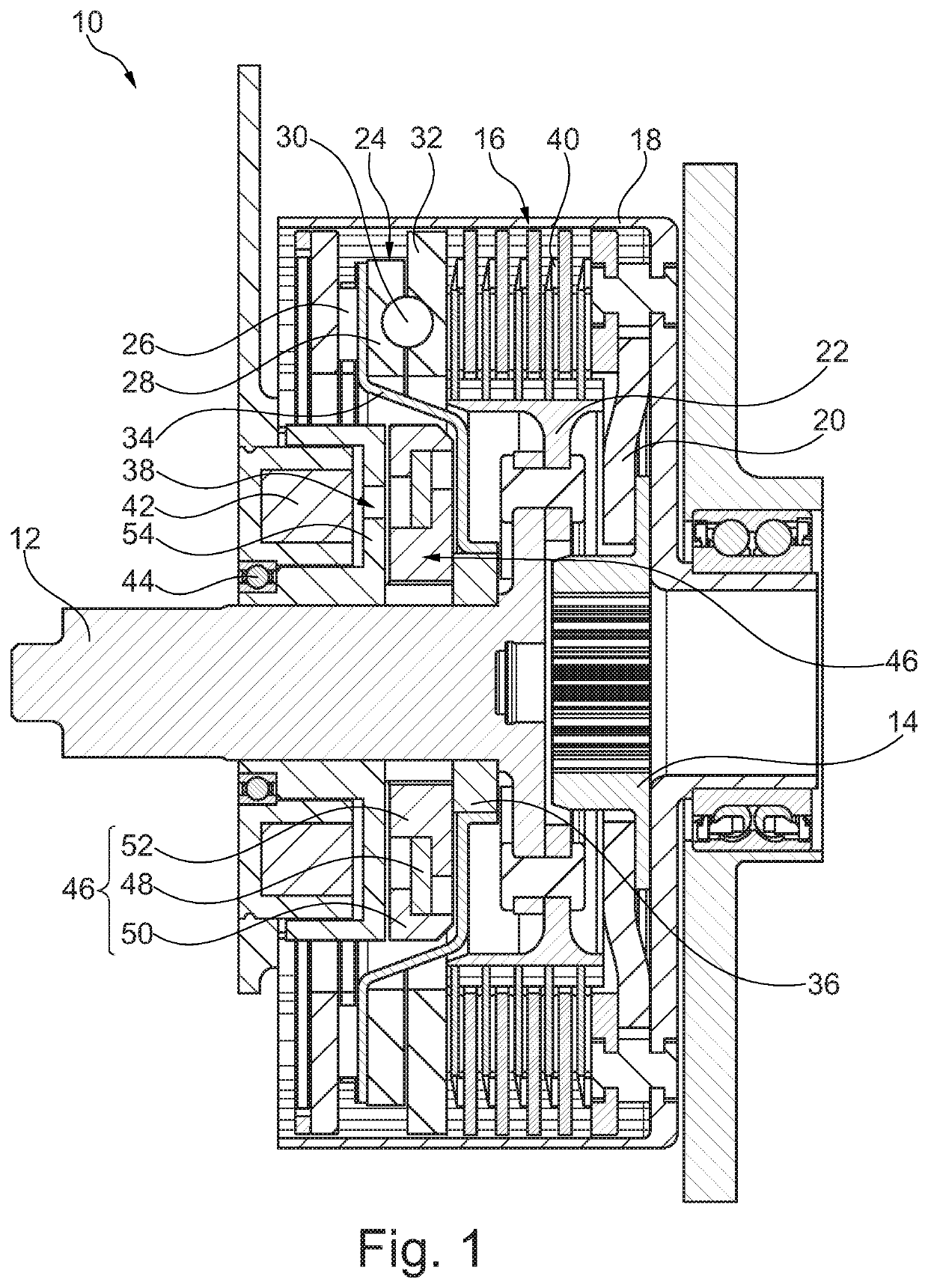
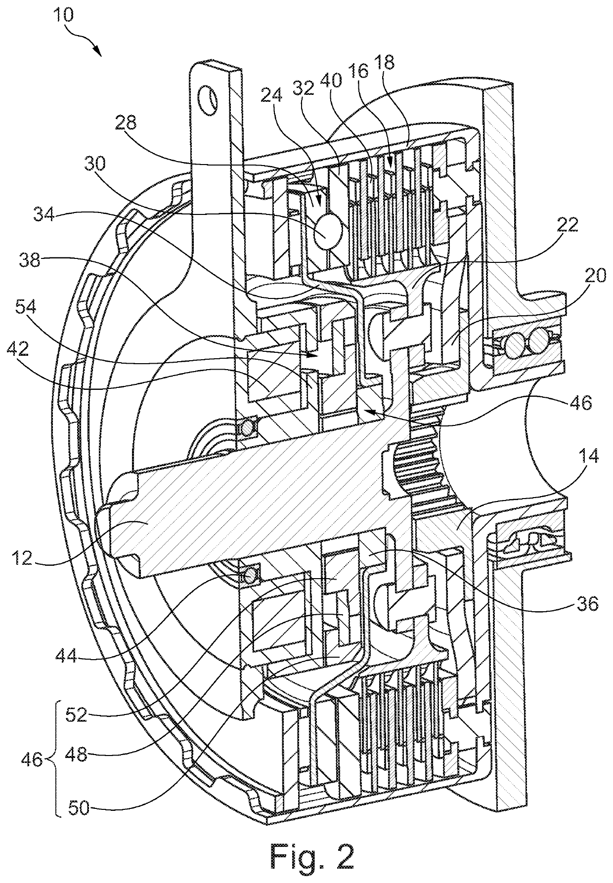
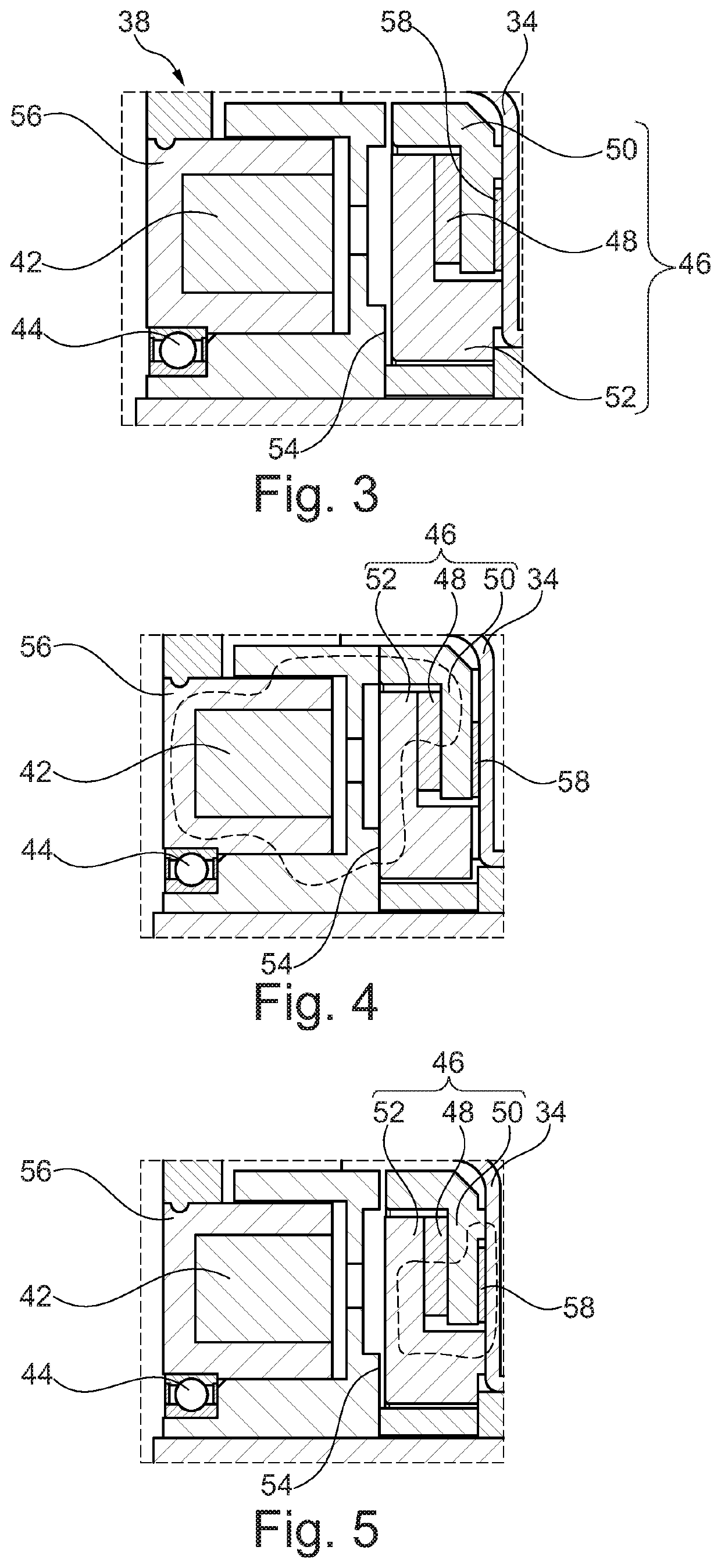
[0027]The clutch system 10 illustrated in FIG. 1 and FIG. 2 has a torque-introducing element 12 in the form of a drive shaft, designed as a crankshaft, of a motor vehicle engine, which torque-introducing element can be coupled for example to a torque-discharging element 14 in the form of a transmission input shaft of a motor vehicle transmission. The torque-discharging element 14 may also be acted on by an electric machine for the purposes of exchanging a torque. For this purpose, the electric machine has a stator which can be flowed through by electrical current and which can interact with a rotor coupled to the torque-discharging element 14. The torque-discharging element may possibly have magnets which interact with the stator, and thereby form the rotor of the electric machine. A separating clutch may be provided between the torque-introducing element 12 and the motor vehicle engine and / or between the torque-discharging element 14 and the motor vehicle transmission, in order to ...


PUM


Abstract

A clutch system for a motor vehicle includes a friction clutch and a magnetic clutch. The friction clutch is for transmitting a torque between a torque-introducing element and a torque-discharging element. The magnetic clutch is for actuating the friction clutch. The magnetic clutch includes an open position and a closed position, an axially displaceable permanent magnet, and an electromagnet for axially displacing the permanent magnet between the open position and the closed position of the magnetic clutch. The electromagnet has an activated state and a deactivated state. The permanent magnet is held magnetically fixed in the open position or in the closed position of the magnetic clutch when the electromagnet is in the deactivated state.

Description

CROSS-REFERENCE TO RELATED APPLICATIONS[0001]This application is the United States National Phase of PCT Appln. No. PCT / DE2017 / 100287 filed Apr. 10, 2017, which claims priority to German Application No. DE102016206675.7 filed Apr. 20, 2016, the entire disclosures of which are incorporated by reference herein.TECHNICAL FIELD[0002]The disclosure relates to a clutch system, with the aid of which a drive shaft of a motor vehicle engine can be coupled to at least one transmission input shaft of a motor vehicle transmission or to a rotor of an electric machine of a hybrid motor vehicle.BACKGROUND[0003]WO 2011 / 050773 A1 has disclosed a clutch system in the form of a so-called booster clutch, in the case of which a friction clutch, designed as a separating clutch, can be actuated with the aid of a ramp system. To close the friction clutch, the ramp system can, with the aid of a plate spring, change its axial extent by means of an output ramp that is rotatable relative to an input ramp, and ...

Claims


Application Information

Patent Timeline
Patent Type & Authority Patents(United States)
IPC IPC(8): F16D27/115B60K6/387F16D23/12F16D27/00
CPCF16D27/115B60K6/387F16D23/12F16D27/004B60Y2200/92F16D2023/123
Inventor FINKENZELLER, MARC
Owner SCHAEFFLER TECH AG & CO KG
Learn More