[0007]Applicants have realized that a smaller, less expensive camera system that requires less light to operate can be implemented, for example, if: 1) an area to be imaged is kept small, and / or 2) relative object motion can be minimized. Such may advantageously allow for lower cost, smaller size, faster tracking, and lower levels of required illumination than existing global shutter imager-based approaches.
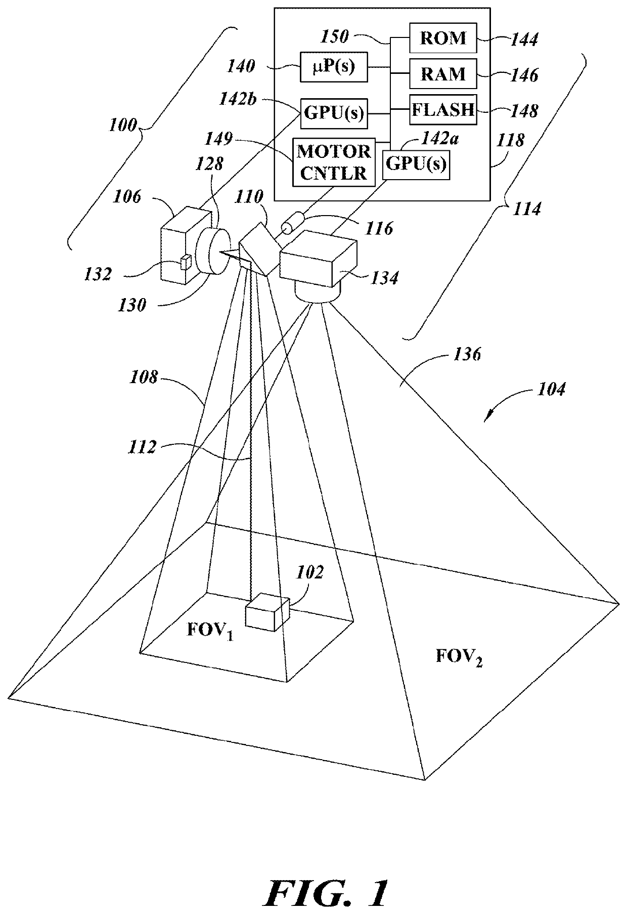
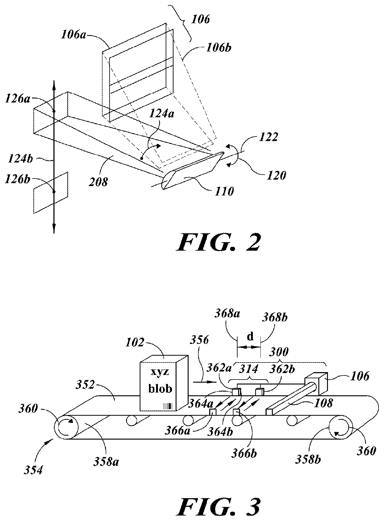
[0008]In at least one implementation, a field-of-view of an imager or camera, for example a rolling shutter camera, is directed or caused to track one or more objects via a steering mirror, for instance a fast steering mirror. A tracking subsystem may include a tracking imager or camera, or some other sensor(s) or transducer(s) that capture data (e.g., 3-dimensional data) that characterizes objects in an environment, for instance a retail environment. In other implementations, images captured by a first imager may be used to determine characteristics of objects, which characteristics are used to cause a respective field-of-view of the first imager to track one or more objects. Characteristics may, for example, include appearance, presence, location, position, speed, and / or direction of travel of the object. Characteristics may also, for example, include physical characteristics of the object and / or packaging, which characteristics allow classifying the object as a certain type of object (e.g., stock keeping unit or SKU, restricted sale type item). The steering mirror directs the field-of-view of a relatively higher resolution imager with a relatively narrow field-of-view to track an object, for example an object spotted in a wider field-of-view of another imager, and / or an object that is in motion. For moving objects, relative motion between the object and the field-of-view of the higher resolution imager is reduced or eliminated, allowing use of a rolling shutter imager or camera.
[0009]Image sensors of rolling shutter imagers typically have smaller pixels than image sensors of global shutter imagers. Rolling shutter imagers typically have lower noise due to the ability to cancel kTC noise, which may otherwise be a dominant noise source. Use of object tracking allows the exposure time of a rolling shutter imager to be longer than would otherwise be possible. Such may advantageously allow use of ambient light or lower levels of active lighting than might otherwise be employed with a global shutter imager.
[0011]The relatively smaller pixel size typical of image sensors of rolling shutter imagers may allow a smaller imager package size, with a shorter focal length lens than might otherwise be required. Typically, for an equivalent f-number, the aperture diameter of a rolling shutter imager is smaller than that of a global shutter imager. This can advantageously reduce cost while increasing tracking speed.
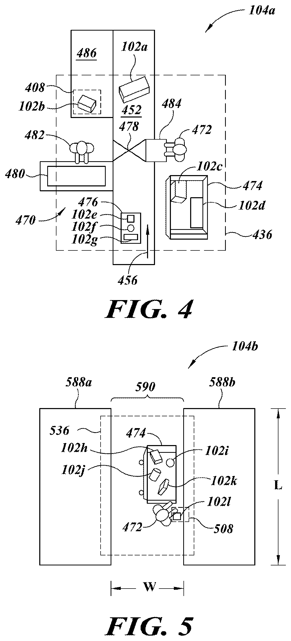
[0013]This approach can be employed, for example, as a security camera in retail (e.g., grocery stores, convenience stores) or other locations, advantageously avoiding the need for additional security cameras. This approach can be employed, for example, to advantageously detect objects or items in a shopping cart, shopping basket, or elsewhere at a checkout station or counter. For instance, objects or items left in a shopping cart or shopping basket may be intentionally or unintentionally removed from the retail environment generating an alert to retail personnel to prevent such from occurring. This approach can additionally or alternatively be employed, for example, to advantageously detect, prevent and otherwise deter what is called “sweet-hearting” by retail personnel such as checkout cashiers or clerks. In “sweet-hearting,” the cashier or clerk intentionally fails to scan or “ring up” an item, for example pretending to scan or “ring the item up,” for customers who are known by or colluding with the cashier or clerk. This allows the customer to steal items in a way that is typically very difficult to detect. Monitoring items at the checkout station or counter, for instance on a conveyer belt, may prevent such. Further, this approach can be employed, for example, to recognize individuals (e.g., customers), including ones that may have previously been banned from the premises, or to provide prompts to personnel allowing customers to be greeted by name or otherwise be recognized. This approach can be employed, for example, to advantageously monitor shopping at locations other than the checkout station or counter of a retail environment. For example, this approach can be employed, for example, to monitor or track the selection of items or objects from shelves and placement into a shopping cart or shopping basket in aisles of a retail environment, allowing better assessment of shopping patterns or purchasing decisions or, conversely, detection of shop lifting. Such could likewise be employed to monitor pick-and-place operations in a warehouse environment, or gaming wagering, card dealing or play in a gaming establishment such as a casino.
[0015]The object tracking subsystem may include a second imager having a second imager field-of-view to capture images of the environment, the first imager field-of-view relatively more narrow than the second imager field-of-view; and a control subsystem, the control subsystem communicatively coupled the second imager to receive information directly or indirectly therefrom, and communicatively coupled to cause the steering mirror to steer the first imager field-of-view based at least in part on information received via the second imager. The object tracking subsystem may detect an entrance of at least a first object into the second field-of-view. The object tracking subsystem may identify an object entering the second field-of-view as corresponding to a defined type of object. The object tracking subsystem may detect an entrance of at least a first object into the first field-of-view. The object tracking subsystem may identify an object entering the first field-of-view as corresponding to a defined type of object. The object tracking subsystem may determine a position of the object. The object tracking subsystem may determine at least an estimate of a speed of the object. The object tracking subsystem may determine a direction of the object. The object tracking subsystem may determine a direction of the object.

