System and method for high accuracy printing on a 3D surface

a technology of high accuracy and printing surface, applied in the direction of printing, other printing apparatus, power drive mechanisms, etc., can solve the problem of dislocation of the first encoder pattern, and achieve the effect of improving personnel safety and being easy to remov

Active Publication Date: 2021-03-09
XYREC IP BV
View PDF17 Cites 1 Cited by
  • Summary
  • Abstract
  • Description
  • Claims
  • Application Information

AI Technical Summary

Benefits of technology

[0008]By measuring and storing inertial data together with associated positional and orientational data of the camera relative to the encoder pattern during the encoder pattern capture run, a measure of the distortion of the encoder pattern on the surface can be determined. The present invention allows to substantially compensate for such distortion of the initial encoder pattern during one or more printing runs, so that the image may be printed on the surface with high accuracy. For instance, when an encoder pattern on the surface has been distorted such that it extends along a curve, then the top edge of an image printed according to the present method may still lie on a substantially straight line, rather than parallel to the curve. Similarly, if the encoder pattern has been distorted by stretching, e.g. non-uniform stretching, during application of the pattern on the surface, then present invention allows the image to be printed substantially without being distorted correspondingly. Thus, by adjusting how the image, or a portion thereof, is printed on the surface during a printing run, based on the data that was measured stored during the encoder pattern capture run, improved accuracy in positioning of the print head may be achieved.
[0011]Preferably, during the encoder pattern capture run the print head is moved across the first swath at a lower speed than during the printing run. By measuring the data during the encoder pattern capture run at a relatively low speed, the effect of structural vibrations of the robot on the measurements may be reduced. Each run in which a swath of the image is printed will be carried out faster, e.g. at least twice as fast, as the encoder pattern capture run.
[0014]In a preferred embodiment the step of providing the initial encoder pattern comprises controlling the printing robot to move the print head across a first swath of the surface while printing the initial encoder pattern on said first swathe. Thus, personnel may maintain a distance to the surface and / or to the robot, while the encoder pattern is applied to the surface. In this manner personnel safety is improved. Additionally, as the printing robot prints the initial encoder pattern on the surface, the camera of the printing robot will also be able to track the initial encoder pattern.
[0015]In alternative embodiment the step of providing the initial encoder pattern comprises either projecting the initial encoder pattern on said first swath of the surface using a light projector that is spaced apart from the printing robot, or attaching a marker strip, which comprises the initial encoder pattern, on the first swath of the surface. In case a light projector is used, the light projector is preferably arranged, when seen in top view, between the base and the surface on which the pattern is projected. In case the marker-strip is used, the marker strip is preferably removably attached to the surface, e.g. by means of an adhesive, so that the strip can easily be removed after the image has been printed on the surface.
[0016]In an embodiment the controller is adapted for controlling the printing robot to position the print head, during the encoder pattern capture run and / or during the printing run, to compensate for high frequency vibrations of the print head based on the inertial data sensed by the IMU during said run.
[0027]In an embodiment the controller is adapted for controlling the printing robot to position the print head, during the encoder pattern capture run and / or during the printing run, to compensate for high frequency vibrations of the print head based on the inertial data sensed by the IMU during said run.

Problems solved by technology

However, when printing the first encoder pattern the print head is subject to structural vibrations, which may result in distortions of the first encoder pattern which can propagate to the image that is printed.

Method used


Image

  • System and method for high accuracy printing on a 3D surface
  • System and method for high accuracy printing on a 3D surface
  • System and method for high accuracy printing on a 3D surface

Examples


Embodiment Construction

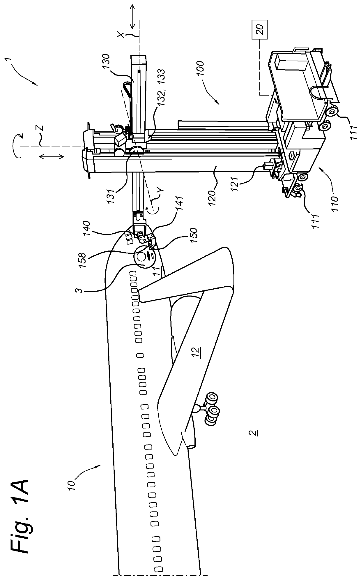
[0033]FIG. 1A schematically shows a perspective view of a printing system 1 according to the invention for printing an image 3 onto one or more curved 3D surfaces 11, 12 of an airplane 10. The system 1 comprises a mobile printing robot 100 and a schematically depicted controller 20 for controlling movement of the robot as well as for controlling ejection of ink from a print head 150 to print a graphic image. The printing robot 100 comprises a base 100 with actuated wheels 111 for driving movement of the robot across floor 2 around the airplane 10. The wheels 111 are connected to the base via a flexible suspension system to allow for smooth driving and stable parking for operations.

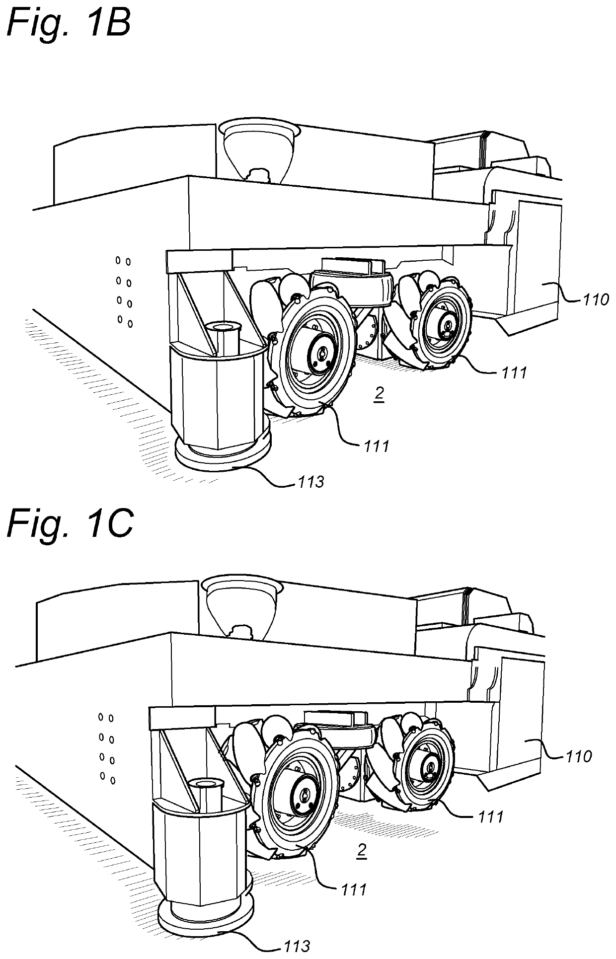
[0034]FIG. 1B shows a detail of the printing robot 100 in a drive mode in which its wheels 111 contact the floor 2 so that the robot can be driven across the floor. The base is further provided with supports, which are spaced apart from the floor 2 when the robot is in the drive mode. FIG. 1C shows the pri...


PUM


Abstract

A method and system for printing an image on a 3D surface is provided, wherein a printing robot is controlled to first carry out an encoder pattern capture run. During this run a print head of the robot is controlled to track an encoder pattern, which may be slightly distorted, on the 3D surface while inertial data from an inertial data measurement unit that is fixed to the print head is stored together with orientational and positional data derived from an image captured of a portion of the encoder pattern that is captured by a camera mounted on the printing head. Next, during a printing run, the print head is controlled such that the camera tracks the encoder pattern for a second time, while printing by the print head and / or a position of the print head is adjusted based on the inertial and orientational and positional data that were stored during the encoder pattern capture run.

Description

FIELD OF THE INVENTION[0001]The present invention relates to a system and method for high accuracy printing on a 3D (three dimensional) surface, in particular a curved 3D surface, using one or more print heads that are mounted on the end of a positioning device.BACKGROUND ART[0002]U.S. patent application Ser. No. 15 / 044,764, which is hereby incorporated by reference, describes a liquid application system comprising: at least one print head that includes: a first liquid ejector to deposit a pigmented liquid on a surface; a second liquid ejector to deposit a liquid on the surface; and at least one image acquisition device; a plurality of actuatable elements operably coupled to the at least one print head; and a print head controller communicably coupled to the first liquid ejector, the second liquid ejector, the plurality of actuatable elements, and the at least one image acquisition device, wherein the print head controller is adapted to: align the first liquid ejector with an encode...

Claims


Application Information

Patent Timeline
Patent Type & Authority Patents(United States)
IPC IPC(8): B41J3/407B41J3/54B41J11/00
CPCB41J3/4073B41J3/543B41J11/008B41J25/001B41J2/2135B25J11/0075B25J19/023B25J5/007B25J9/041B25J9/06
Inventor LEWIS, CHRISTOPHER L.ROBINSON, MATTHEW M.EVANS, PAUL T.BOEIJINK, PETERBROCKSCHMIDT, BRANSON P.
Owner XYREC IP BV
Why Eureka
Try Eureka