Supression of cross current in a plural converter system
a converter system and cross current technology, applied in the direction of control system, electric motor control, conversion with intermediate conversion to dc, etc., can solve the problem of unbalanced output current of each apparatus
- Summary
- Abstract
- Description
- Claims
- Application Information
AI Technical Summary
Benefits of technology
Problems solved by technology
Method used
Image

Examples
embodiment 1
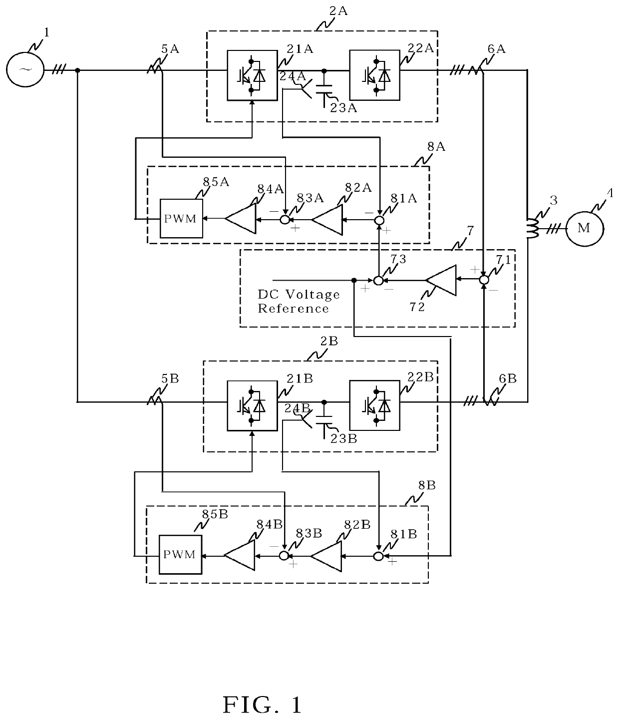
[0015]FIG. 1 is the circuit configuration diagram of the power conversion system according to the first embodiment of the present invention. A commercial three-phase AC power supply 1 is connected to converters 21A and 21B of power conversion apparatuses 2A and 2B via current detectors 5A and 5B, respectively. The power conversion apparatuses 2A and 2B include converters 21A and 21B, DC capacitors 23A and 23B, and inverters 22A and 22B, respectively. DC output voltages of converters 21A and 21B are smoothed by DC capacitors 23A and 23B, and they are inputted to inverters 22A and 22B, respectively. The AC outputs of the inverters 22A and 22B are connected to one and the other terminals of the coupling reactor 3 provided between each phase of the AC output via current detectors 6A and 6B, respectively. The three-phase output at the middle point of the coupling reactor 3 is connected to the AC motor 4. With the above configuration, power conversion apparatuses 2A and 2B drive AC motor ...
embodiment 2
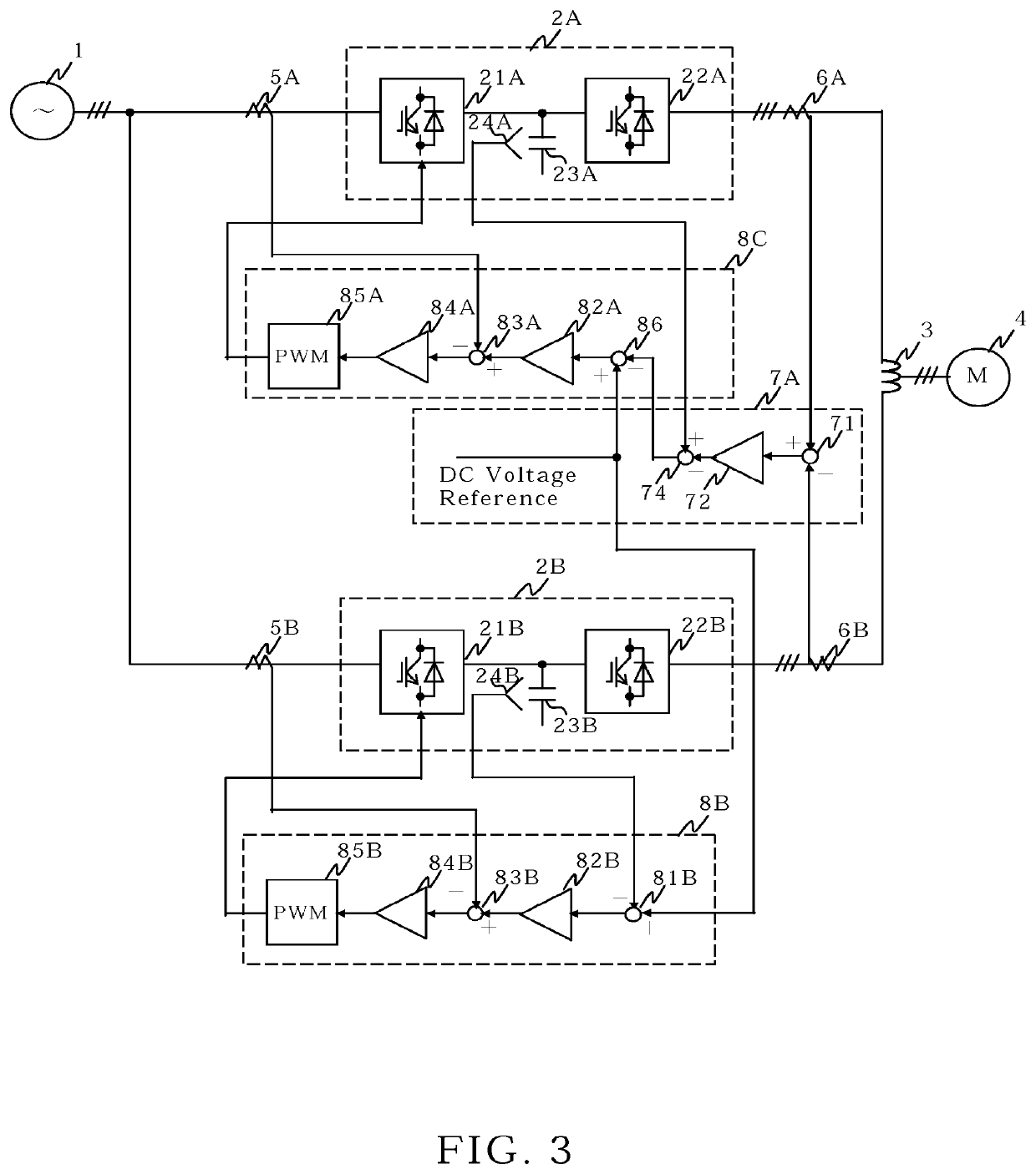
[0024]FIG. 3 is the circuit configuration diagram of the power conversion system according to the second embodiment of the present invention. Regarding each part of the second embodiment, the same parts as those of the power conversion system according to the first embodiment of the present invention in FIG. 1 are denoted by the same reference numerals, and description thereof will be omitted. The difference between the second embodiment and the first embodiment is followings. First, in the difference current control unit 7A, the subtractor 74 calculate the difference between the DC voltage feedback correction amount outputted from the difference current controller 72 and the DC voltage detected by the voltage detector 24A, and gives the output as corrected DC voltage feedback to the subtraction input of a subtractor 86 of the control unit 8C. Second, DC voltage reference is given to the addition input of the subtractor 86, and the difference between the DC voltage reference and the...
embodiment 3
[0026]FIG. 4 is the block diagram of a power conversion system according to Embodiment 3 of the present invention. The AC power supply 1 supplies an AC voltage to the primary winding of an input transformer 1A. The input transformer 1A is a secondary multi-winding transformer, and has six secondary windings in this embodiment. From each of these secondary windings, a three-phase or single-phase secondary voltage is supplied to each converter of the power conversion apparatuses 2C, 2D, 2E, 2F, 2G, and 2H. Each inverter of the power conversion apparatuses 2C, 2D, 2E, 2F, 2G, and 2H is a single-phase inverter. Inverter output of the power conversion apparatuses 2C and 2D, 2E and 2F, and 2G and 2H are connected in parallel via the coupling reactors 3A, 3B and 3C, respectively. The midpoint of each of the coupling reactors 3A, 3B, and 3C is connected to the U-phase, V-phase, and W-phase input terminals of the AC motor 4, respectively.
[0027]Even in the power conversion system having the c...
PUM
 Abstract
Description
Claims
Application Information
 - R&D
- Intellectual Property
- Life Sciences
- Materials
- Tech Scout
- Unparalleled Data Quality
- Higher Quality Content
- 60% Fewer Hallucinations
Browse by: Latest US Patents, China's latest patents, Technical Efficacy Thesaurus, Application Domain, Technology Topic, Popular Technical Reports.
© 2025 PatSnap. All rights reserved.Legal|Privacy policy|Modern Slavery Act Transparency Statement|Sitemap|About US| Contact US: help@patsnap.com