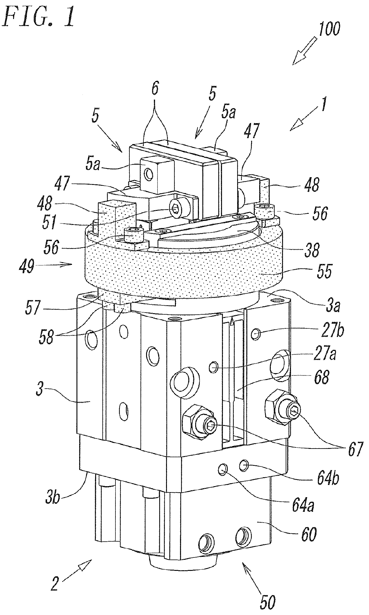
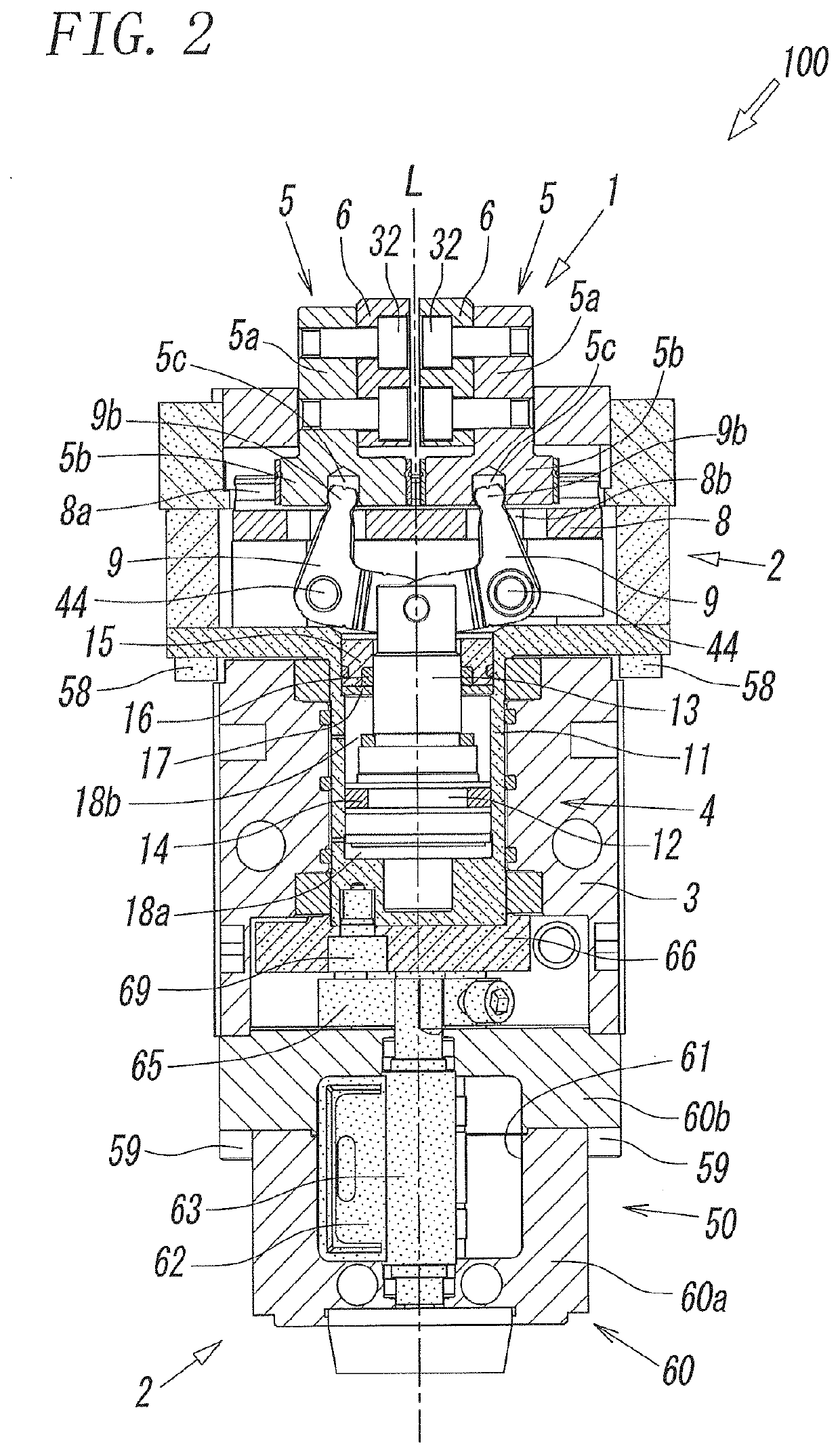
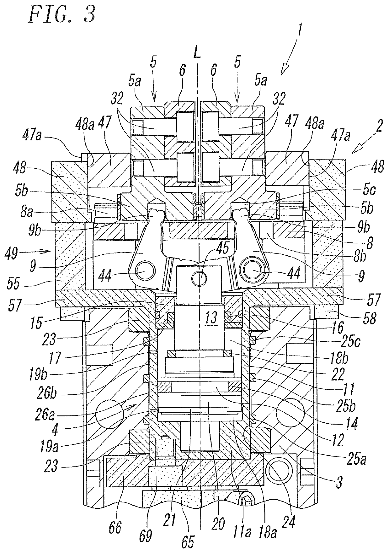
Air chuck provided with locking mechanism
a technology of locking mechanism and air chuck, which is applied in the field of air chucks, can solve the problems of loss of gripping force of fingers, and work is moved or dropped, so as to prevent damage to work or damage or the like of devices around the work due to dropping the work, and ensure the safety of the operator
- Summary
- Abstract
- Description
- Claims
- Application Information
AI Technical Summary
Benefits of technology
Problems solved by technology
Method used
Image
Examples
second embodiment
[0086]Also, in the drawings for the second embodiment, for ease of understanding, components displaced (rotated) integrally with the first locking members 47, 47 are dotted.
[0087]A rail holder 201 is formed at the upper end portion of the cylinder tube 11. The rail holder 201 has a cylindrical shape having a larger diameter than that of the cylinder tube 11. A step portion 202 extending in the diameter direction of the rail holder 201 is formed at an upper end portion of the rail holder 201. The support rail 8 is secured to the cylinder tube 11 by placing the support rail 8 on the step portion 202 and screwing the rail securing screws 41, which are inserted through screw insertion holes of the support rail 8, into screw holes 204 of the step portion 202. The width and depth of the step portion 202 are substantially the same as the width and height of the support rail 8.
[0088]Although the above-described rail holder 201 is integrally formed with the cylinder tube 11, the rail holder ...
third embodiment
[0100]Also, in the drawings for the third embodiment, for ease of understanding, components displaced (rotated) integrally with the cylinder tube 11 are dotted.
[0101]As clearly understood from FIGS. 18 and 19, a first locking member 47 is formed by the engagement pin 45 through which the rod 13 and the pair of open / close levers 9, 9 are coupled to one another. That is, the first locking member 47 has a shaft shape having a circular shape in section, extends in a direction perpendicular to the axial line L, and also serves as the engagement pin 45. Furthermore, the length of the first locking member 47 is larger than the diameter of the cylinder tube 11, and both ends of the first locking member 47 project outward from the outer circumference of the cylinder tube 11. Retaining portions 47A at which the second locking members 48, 48 are retained are formed in these projected end portions of the first locking member 47. Both the end portions of the first locking member 47 are fitted in...
first embodiment
[0107]The structures of the air chuck 300 other than the above description are substantially the same as the structures of the air chuck 100 according to the
[0108]The structures related to the positioning screws 309 and the single adjusting bolt 67 in the air chuck 300 according to the third embodiment can also be applied to the air chuck 100 according to the first embodiment and the air chuck 200 according to the second embodiment.
[0109]Next, operations of the air chuck 300 are described. FIG. 22 illustrated a state in which the pair of fingers 5, 5 are opened, and accordingly, the work W is not gripped. At this time, the first locking member 47 occupies a raised position due to advancing (moving upward) of the rod 13, and the second locking members 48 occupy non-locking positions separated from the first locking member 47.
[0110]When gripping the work W from this state by using the pair of fingers 5, 5, as illustrated in FIGS. 23 and 24, the rod 13 is retracted (moved downward) by ...
PUM
| Property | Measurement | Unit |
|---|---|---|
| circumference | aaaaa | aaaaa |
| diameter | aaaaa | aaaaa |
| gripping force | aaaaa | aaaaa |
Abstract
Description
Claims
Application Information
 - R&D
- Intellectual Property
- Life Sciences
- Materials
- Tech Scout
- Unparalleled Data Quality
- Higher Quality Content
- 60% Fewer Hallucinations
Browse by: Latest US Patents, China's latest patents, Technical Efficacy Thesaurus, Application Domain, Technology Topic, Popular Technical Reports.
© 2025 PatSnap. All rights reserved.Legal|Privacy policy|Modern Slavery Act Transparency Statement|Sitemap|About US| Contact US: help@patsnap.com


