Environment control apparatus

a technology of environment control and memory chips, which is applied in the direction of electronic circuit testing, measurement devices, instruments, etc., can solve the problems of high cost, high electricity consumption, and long testing time of memory chips, and achieve the effect of improving the problems associated

Active Publication Date: 2021-03-23
ONE TEST SYST
View PDF5 Cites 17 Cited by
  • Summary
  • Abstract
  • Description
  • Claims
  • Application Information

AI Technical Summary

Benefits of technology

[0006]In response to the above-referenced technical inadequacies, the present disclosure provides an environment control apparatus to effectively improve the issues associated with conventional memory chip testing apparatuses (e.g., the conventional memory chip testing apparatus cannot be used to test two groups of memory chips that need to be respectively tested by two different testing processes).

Problems solved by technology

A conventional memory chip testing apparatus is provided for testing a large number of memory chips, so that the operation of the conventional memory chip testing apparatus needs to consume a lot of electricity that generates high cost.
In addition, during a same period of time, the conventional memory chip testing apparatus is only used to perform a predetermined testing process on the same group of memory chips.
Therefore, the testing time of the memory chips is too long.

Method used


Image

  • Environment control apparatus
  • Environment control apparatus
  • Environment control apparatus

Examples


first embodiment

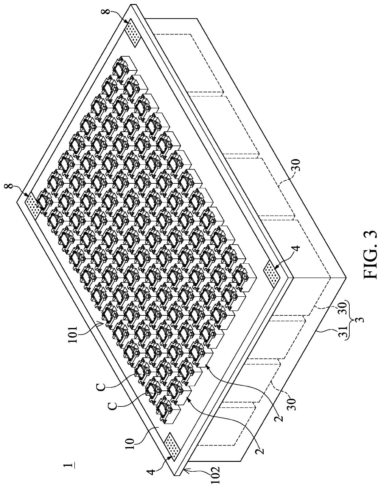
[0090]FIG. 16 is a flow chart of a chip testing method according to the present disclosure. The chip testing system E can perform the predetermined testing process on the chips C by implementing the following chip testing method. The chip testing method includes: a chip mounting step S1 implemented by using the chip mounting apparatus E2 to respectively dispose a plurality of chips C from a tray onto the electrical connection sockets 2 of the chip testing device 1; a moving-in step S2 implemented by transferring the chip testing device 1 carrying the chips C into one of the accommodating chambers E311 of one of the environment control apparatuses E3; a temperature adjusting step S3 implemented by controlling an operation of the temperature adjusting device E34 in the one of the accommodating chambers E311 so that the chips C are in an environment having a predetermined temperature; a testing step S4 implemented by providing electricity to the chip testing device 1 in the one of the ...

third embodiment

[0094]FIG. 18 is a flow chart of a chip testing method according to the present disclosure. The chip testing method in the present embodiment further includes a separating step S5 that is between the testing step S4 and the moving-out step S6 and is not disclosed in the above embodiments. Moreover, the separating step S5 is implemented by separating the first power supply member 4 of the chip testing device 1 from the chamber terminals of the second power supply member E33 of the one of the accommodating chambers E311 after the predetermined testing process for the chips C connected to the chip testing device 1 is finished.

[0095]As shown in FIG. 3, FIG. 9, and FIG. 10, the environment control apparatus E3 further includes a plurality of lift devices E38, and each of the accommodating chambers E311 is provided with one of the lift devices E38 therein. Each of the lift devices E38 is connected to the central control device E1. Each of the lift devices E38 is controllable by the centra...

fourth embodiment

[0106]FIG. 19 is a flow chart of a chip testing method according to the present disclosure. The chip testing system E of the present embodiment is configured to test a plurality of memory chips (i.e., the chips C) by implementing the chip testing method. The difference between the chip testing method in the present embodiment and other embodiments of the present disclosure is described as follows. In the present embodiment, the temperature adjusting step S3 and the testing step S4 can be repeatedly implemented for two times after the moving-in step S2 and before the moving-out step S5, and include a temperature adjusting step S31, a testing step S41, a temperature adjusting step S32, and a testing step S42.

[0107]In the temperature adjusting step S31 and the testing step S41 (i.e., the temperature adjusting step S3 and the testing step S4 are implemented for a first time of the two times), the temperature adjusting device E34 in the accommodating chamber E311 is controlled so that th...


PUM


Abstract

An environment control apparatus includes an apparatus body, a processing device, and a plurality of temperature adjusting devices. The apparatus body includes a plurality of accommodating chambers each having one of the temperature adjusting devices. Each of the temperature adjusting devices has a heater and a cooler. When a chip testing device carrying a plurality of chips is arranged in one of the accommodating chambers, the chip testing device is supplied with electricity, and the heater and the cooler of the corresponding temperature adjusting device are controlled to operate, the chip testing device performs a testing process on the chips disposed thereon.

Description

CROSS-REFERENCE TO RELATED PATENT APPLICATION[0001]This application claims the benefit of priority to Taiwan Patent Application No. 108125186, filed on Jul. 17, 2019. The entire content of the above identified application is incorporated herein by reference.[0002]Some references, which may include patents, patent applications and various publications, may be cited and discussed in the description of this disclosure. The citation and / or discussion of such references is provided merely to clarify the description of the present disclosure and is not an admission that any such reference is “prior art” to the disclosure described herein. All references cited and discussed in this specification are incorporated herein by reference in their entireties and to the same extent as if each reference was individually incorporated by reference.FIELD OF THE DISCLOSURE[0003]The present disclosure relates to an environment control apparatus, and more particularly to an environment control apparatus ...

Claims


Application Information

Patent Timeline
Patent Type & Authority Patents(United States)
IPC IPC(8): G01R31/28
CPCG01R31/2875G01R31/2877G01R31/2891G01R1/0458G01R1/07314G01R31/2863G01R31/2874G01R31/2893
Inventor TSAI, CHEN-LUNGROSENTHAL, GENE
Owner ONE TEST SYST
Why Eureka
Try Eureka