Systems and methods for affixing a prosthesis to tissue

a prosthesis and tissue technology, applied in the direction of nail, surgical staple, fastening means, etc., can solve the problems of limiting the benefits of the procedure, affecting the healing effect of the prosthesis, so as to reduce the risk of erosion, facilitate faster recovery time, and minimize the effect of adverse outcomes

Active Publication Date: 2021-03-30
MICRO INTERVENTIONAL DEVICES
View PDF220 Cites 11 Cited by
  • Summary
  • Abstract
  • Description
  • Claims
  • Application Information

AI Technical Summary

Benefits of technology

[0016]The device and surgical methodology described below can be considered as having three main components: a deployment mechanism, an anchor and a prosthesis. Together, these three features can be used to reliably reach and secure the prosthetic valve to the soft tissues of the human heart, such that the prosthesis can address ailments such as heart valve insufficiency or stenosis. Per their unique designs, the low-profile deployment system ensures that the surgery is minimally invasive, while the TCAT (Trans-catheter Anchoring Technology) anchors serve to overcome the aforementioned structural and functional difficulties of securing a prosthesis to locations such as the mitral valve.
[0017]Where radial pressure has proven a viable means of securement for aortic valve prosthesis, anchors will serve as the most efficient method of securement in mitral valve replacement. The design of the anchor addresses various problems associated with anchoring or suturing a prosthesis within the heart. First, the tension component serves a dual purpose in the anchor's design: it pulls the anchor head component in a distal direction after deployment, allowing the barbs to set more securely, and also allows for the prosthesis to remain in more constant contact with the tissues of the heart, despite their fluctuating throughout the cardiac cycle. This means that where other anchoring technologies, or suturing methods, require tensioning in order to most effectively secure a prosthesis to the implant site, the anchor tensions itself. This allows for a procedure to be completed on a level of significantly less invasiveness to the patient, encouraging faster recovery times and minimizing detrimental outcomes.
[0018]Moreover, the proprietary design of the anchor, namely with regard to its tension component, may overcome a number of difficulties presented by valve replacement surgeries, particularly in the case of mitral valve replacement. That is, this design is better suited to encourage constant contact between a prosthesis and the tissues of the heart, particularly when those tissues expand and contract. The anchor design is also better suited to pull the tissues surrounding the mitral valve into apposition with the prosthesis, thereby reducing health risks associated with blood flowing around the exterior perimeter of the prosthesis. In other words, when the walls surrounding the mitral valve dilate during the cardiac cycle, the tension spring component can counter that outward force, so as to minimize gaps that would be created whilst minimizing potential damage to the soft tissues surrounding the anchors' barbs.
[0020]Further described below is a compliant valve using active fixation (i.e., the anchor deployment) to affix the valve to the native heart tissue. The prosthetic valve described below may include varying rigidity, e.g., by varying the wall thickness of the frame making up the valve. The valve may be compliant on the inflow side, above a more rigid annular ring, and even more rigid leaflet posts or struts. If the valve is soft and malleable on its inflow side, when the prosthesis is applied to native tissue in a heart valve, the prosthesis may form its shape to the shape of the native tissue. The benefits of such a malleable valve include a better seal of the valve inflow track, which allows for improved tissue in-growth into the prosthetic. Further, the more rigid annular cells and leaflet posts allow for greater support at the outflow side of the valve, where the valve fatigue is greatest.
[0030]The plurality of the inflow cells may extend radially in a distal direction. Each of the anchor receptacles may be configured to receive an anchor including a distal end tapered to a distal tip configured to pierce and anchor into tissue, a proximal head, and a tension component, situated between the distal end and the proximal head, wherein the anchor receptacles are large enough to permit the passage of the distal end of the anchor through the anchor receptacle and into surrounding tissue, and small enough to prevent the passage of the proximal head through the anchor receptacle, such that, after deployment of the anchor the tension component is situated in a tensioned state against the anchor receptacle and the tissue to bring the prosthetic valve into apposition with the tissue.

Problems solved by technology

For example, percutaneous repair involves modified surgical techniques, which can limit the benefits of the procedure.
Annular rings may lack effectiveness, and include risks of erosion, perforation, and coronary artery thrombosis.
Edge-to-edge repair can be technically demanding, and may lack long term durability.
Depending upon the particular valve failure, combinations of different repair techniques may be necessary, further complicating the procedure and limiting its effectiveness.
Open surgery solutions for heart valve replacement, however, carry significant risks to the patient.
Moreover, fixing the heart valve implant to the implant site may be challenging, as the implant site may form an irregular shape, may lack calcium to secure the valve, or may cause difficulty in fixing the implant valve with the proper orientation.
Further, although long-standing surgical methods for the implantation and the design of aortic valve prosthesis have proven both safe and reliable over the past few decades, it has been well documented that the transition of these same prosthetic designs and surgical methods, to mitral valve replacement, has fallen far short both in terms of safety and reliability.
But, the mitral valve lacks the necessary rigidity and consistency of size that allow radial pressure to succeed as a means of engagement in the aortic arena.
The ineffectiveness of radial pressure to reliably secure a prosthesis in certain cardiac procedures has also had implications regarding the invasiveness of those procedures.
Another dilemma in prosthetic related cardiac surgeries results from the drastic structural variance between individual hearts when circumstances dictate that radial pressure will not serve as an adequate means of securement.
Furthermore, the depth required for a certain anchor or suture to reliably affix a prosthesis is often not present between the operable tissue and these fragile structures.
The potential health risks created by this dilemma have not been sufficiently addressed by the current technologies in this space, and it is difficult to envision an anchoring technology that would maintain a deployment depth necessary to consistently secure a prosthesis without running the risk of damaging nearby cardiac features.
The drawbacks associated with the heightened level of invasiveness and the implications of structural inconsistences are two of many problems yet to be solved for the growing number of cardiac patients in the world today.
Previous anchor devices employing a threaded screw, for example, will not properly anchor into soft tissue.

Method used


Image

  • Systems and methods for affixing a prosthesis to tissue
  • Systems and methods for affixing a prosthesis to tissue
  • Systems and methods for affixing a prosthesis to tissue

Examples


Embodiment Construction

[0103]As set forth in greater detail below, example embodiments of the present invention allow for the effective and reliable deployment of specially designed TCAT anchors, by means of a proprietary catheter-based delivery mechanism, for the purposes of securing a prosthesis to the tissues of the human heart.

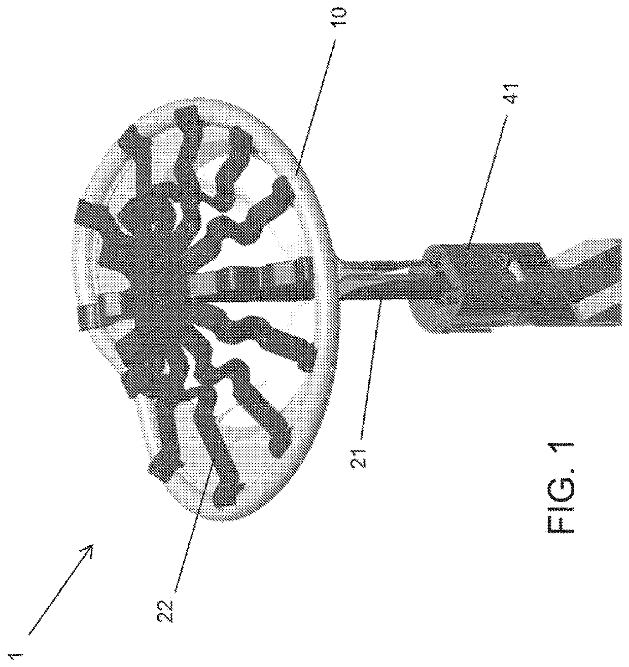
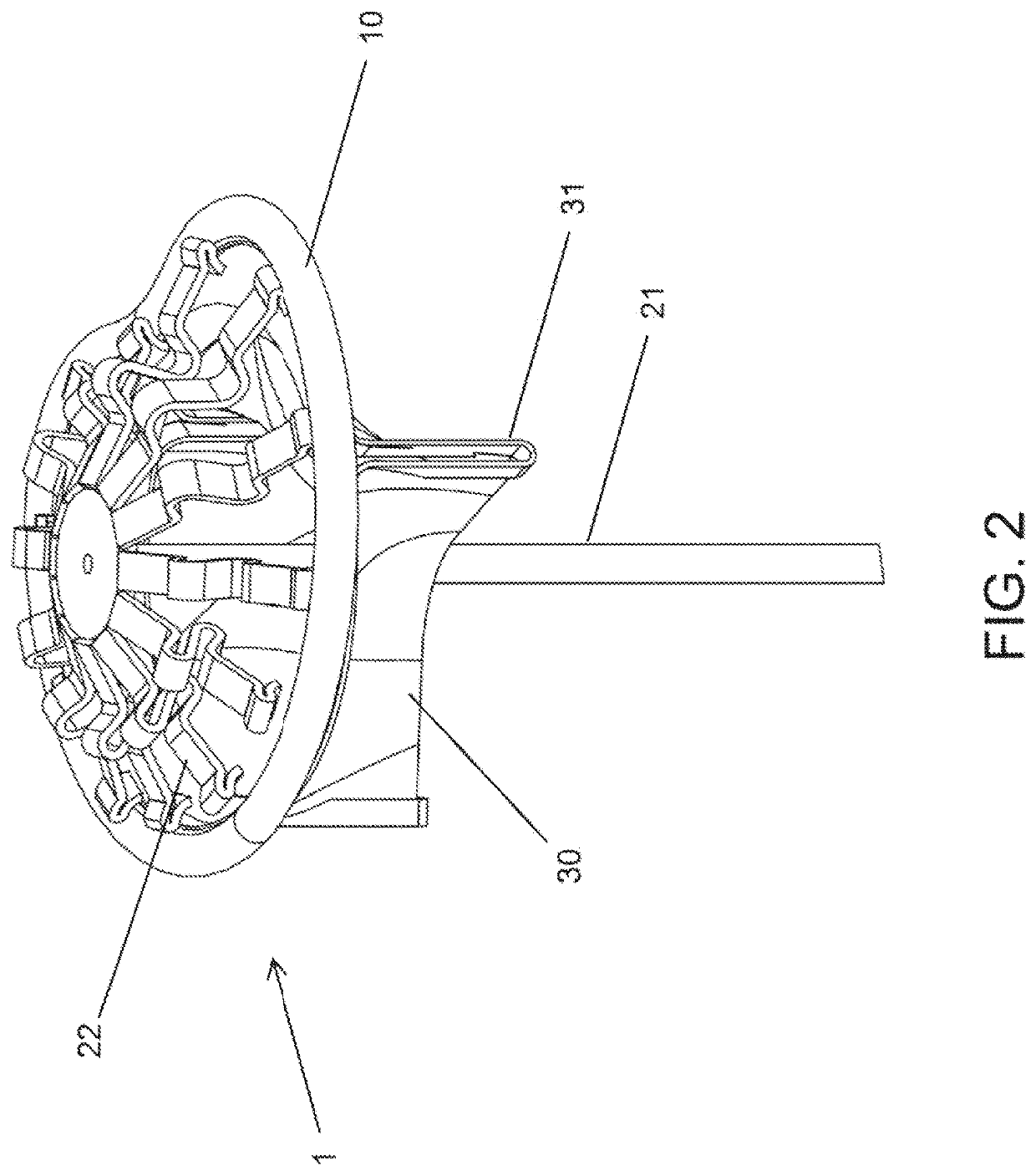
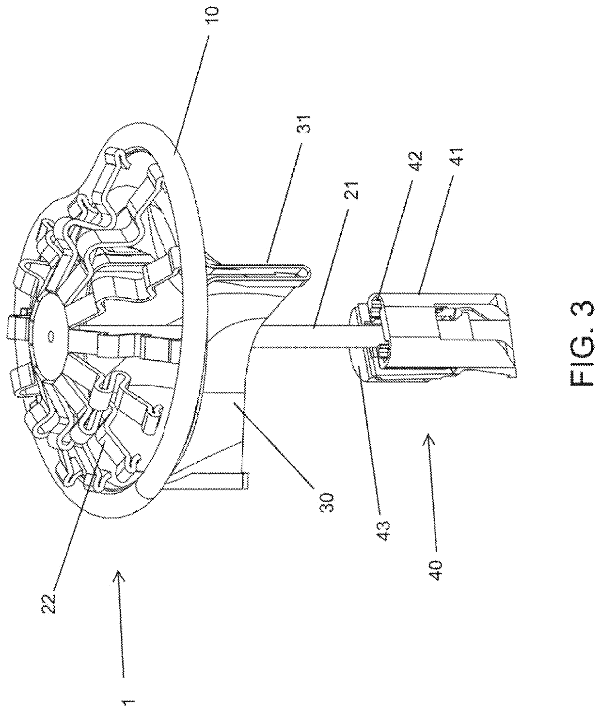
[0104]FIG. 1 illustrates heart valve replacement prosthesis 1 having ring 10, which, in an exemplary embodiment, may be elastic. FIG. 1 further illustrates applicator 20 having applicator shaft 21 and spring arms 22. Spring arms 22 may be affixed to the distal end of the applicator shaft 21, and may connect the distal end of the applicator shaft 21 to the ring 10 of the replacement prosthesis 1. FIG. 1 further illustrates driver 40, as will be described in more detail below.

[0105]As will be generally understood, as described by, for example, U.S. Pat. No. 7,621,948, the entirety of which is hereby incorporated by reference as if fully disclosed herein, the replacement prosthesis...


PUM


Abstract

Systems and methods recited herein provide for affixation of a prosthetic valve to surrounding tissue, by at least one anchor and an anchor deployment device. The prosthetic valve device may be compliant with native tissue and may receive the at least one anchor in at least one anchor receptacle to affix the prosthetic valve to native tissue. The anchor may include a distal tip, a proximal head, and a tension component, such that upon deployment into tissue the tension component is situated in a tensioned state to exert a pulling force on the distal end of the anchor.

Description

CROSS-REFERENCE TO RELATED APPLICATIONS[0001]This application claims the benefit of the filing date of, and incorporates by reference thereto in its entirety, U.S. Provisional Patent Application Ser. No. 62 / 088,680, filed on Dec. 7, 2014.[0002]This application is also a continuation-in-part of, claims the benefit of the filing date of, and incorporates by reference thereto in its entirety, U.S. patent application Ser. No. 14 / 737,408, filed Jun. 11, 2015, which claims the benefit of the filing date of U.S. Provisional Patent Application Ser. No. 62 / 010,680, filed on Jun. 11, 2014, and which is also incorporated by reference herein in its entirety.[0003]Further, each of the following is hereby incorporated by reference thereto in its entirety: U.S. patent application Ser. No. 14 / 321,476, filed Jul. 1, 2014, U.S. patent application Ser. No. 14 / 301,106, filed Jun. 10, 2014, U.S. patent application Ser. No. 13 / 843,930, filed Mar. 15, 2013, PCT Application No. PCT / US14 / 30868, filed Mar. 1...

Claims


Application Information

Patent Timeline
Patent Type & Authority Patents(United States)
IPC IPC(8): A61F2/24A61B17/068A61B17/064
CPCA61F2/2418A61B17/068A61F2/2409A61B2017/0647A61F2/2427
Inventor WHITMAN, MICHAEL P.
Owner MICRO INTERVENTIONAL DEVICES
Why Eureka
Try Eureka