
Ion thruster with external plasma discharge
a technology of plasma discharge and thruster, which is applied in the direction of cosmonautic vehicles, machines/engines, transportation and packaging, etc., can solve the problems of component wear, relatively limited thrust of thrusters, and limited lifetime of thrusters, so as to achieve the effect of reducing the wear of components
Patent Information
- Authority / Receiving Office
- US · United States
- Patent Type
- Patents(United States)
- Current Assignee / Owner
- Publication Date
- 2021-03-30
Smart Images
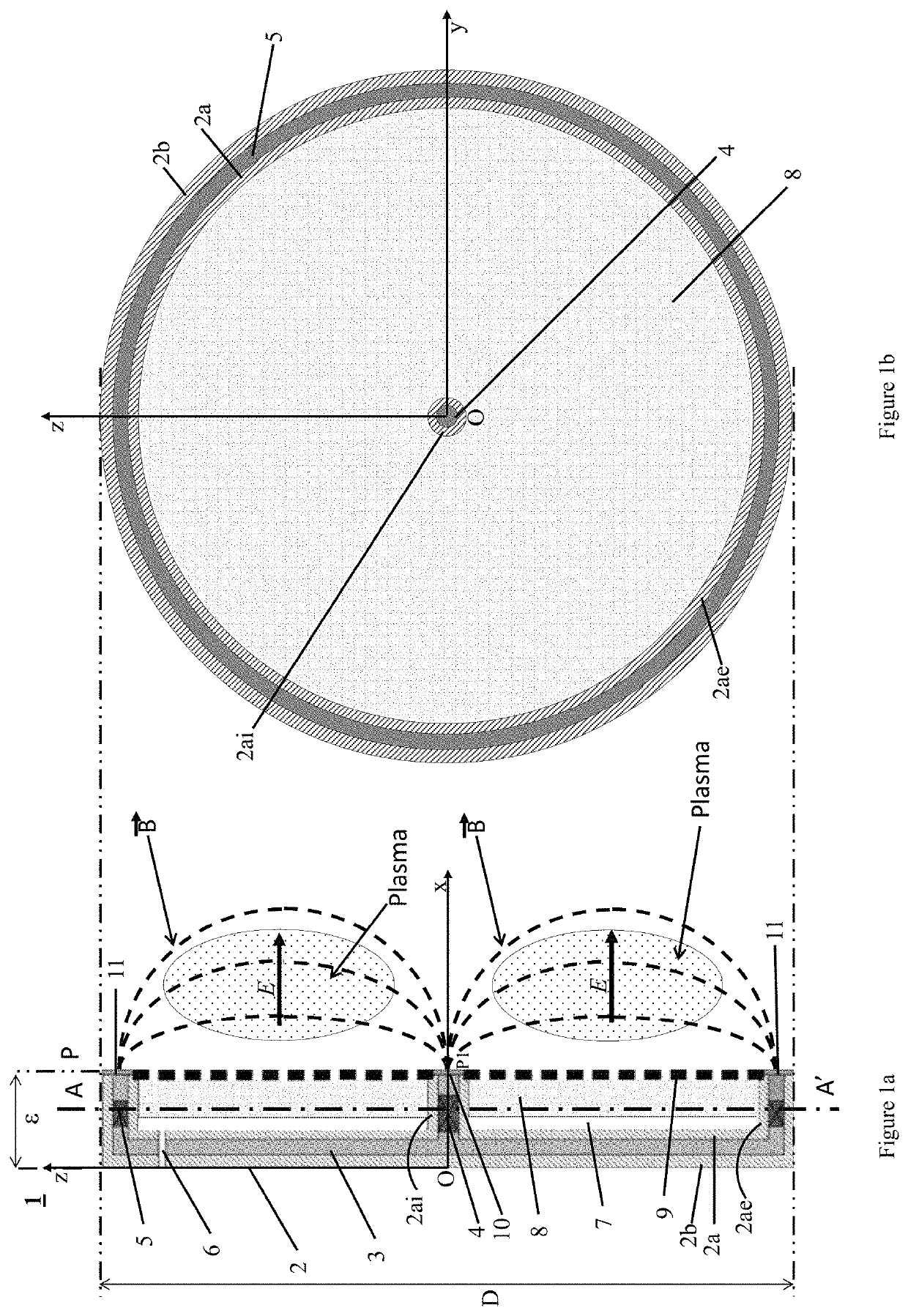
Figure 1 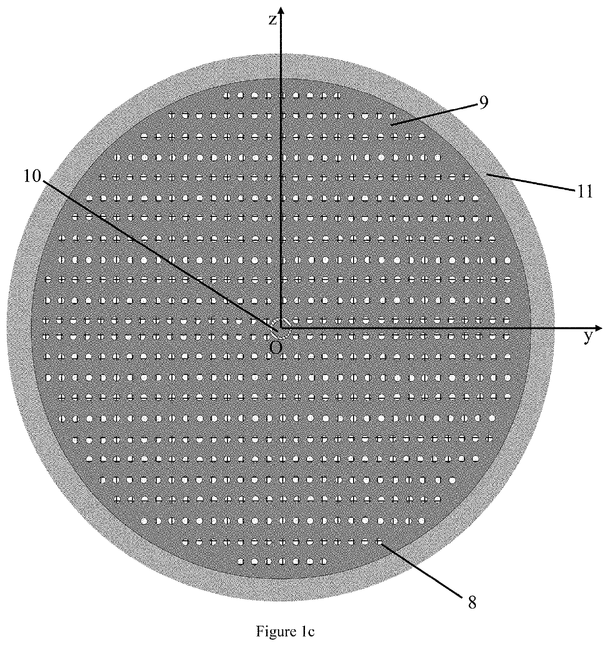
Figure 2 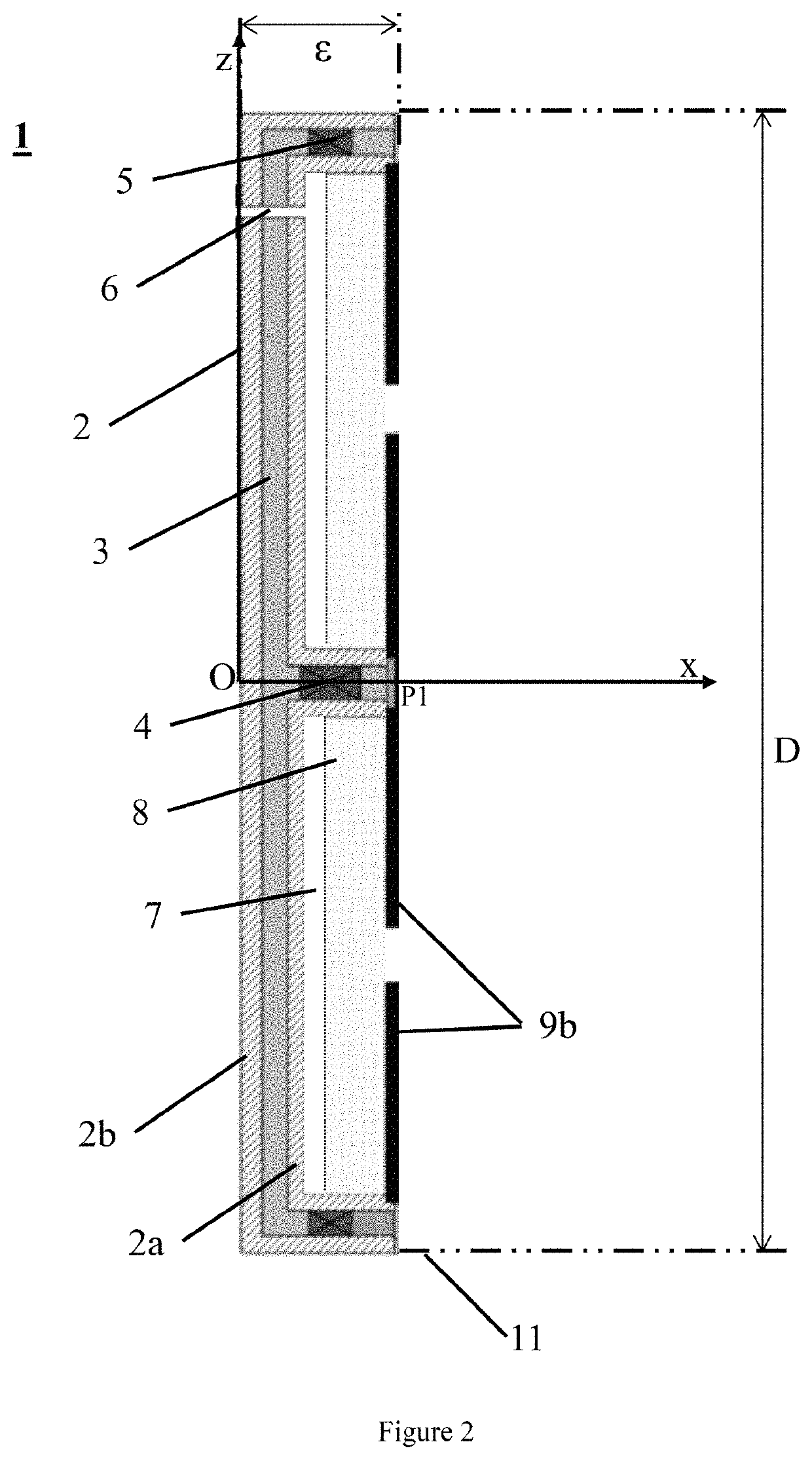
Figure 3
Abstract
Description
CROSS-REFERENCE TO RELATED APPLICATIONS
[0001] This application is a National Stage of International patent application PCT / FR2017 / 052789, filed on Oct. 11, 2017, which claims priority to foreign French patent application No. FR 16 59808, filed on Oct. 11, 2016, the disclosures of which are incorporated by reference in their entirety.FIELD OF THE INVENTIONBACKGROUND
[0002] Ion thrusters, also called plasma or electric thrusters, for space vehicles, allow fuel consumption to be significantly decreased by virtue of a high ejection speed of the latter. However, these thrusters, as opposed to chemical thrusters, have a relatively limited thrust. Thus, they must operate for a very long time, possibly for as much as several years of cumulative firing, in order to allow the space vehicle to achieve a high final speed. The lifetime of ion thrusters is therefore a criterion of primary importance. This lifetime is limited by wear of components, in particular wear of the system for generating the ...
Examples
Embodiment Construction
[0023]The present invention is described below with reference to FIGS. 1 to 3.
[0024]According to a first aspect, the present invention relates to an ion thruster 1 comprising:
[0025]a body 2 having a symmetry of revolution about an axis of revolution (Ox) and having the general shape of a capital E in a cross section in a plane passing through the axis of revolution (Ox), the body 2 comprising within it a magnetic circuit 3, an element 4 that generates a magnetic field and an annular element 5 that generates a magnetic field, said element 4 being placed in the cross section in the central arm of the capital E, and said annular element 5 having a symmetry of revolution about the axis of revolution (Ox) and being placed in the cross section in the upper and lower arms of the capital E, the element 4 and the annular element 5 having an opposite magnetic polarity,
[0026]an anode 9 covering an internal annular space 7, said annular space having a symmetry of revolution about the axis of re...