
Sensor device, sensor system, and information processing device

a sensor and information processing technology, applied in the direction of speed/acceleration/shock measurement devices, navigation instruments, instruments, etc., can solve the problems of fatal accumulated errors and errors in sensor information measured by a sensor device, and achieve the effect of reducing fatal accumulated errors in sensors

Active Publication Date: 2021-04-13
SONY CORP
View PDF11 Cites 0 Cited by
  • Summary
  • Abstract
  • Description
  • Claims
  • Application Information

AI Technical Summary

Benefits of technology

[0010]As described above, according to the present disclosure, a mechanism that can easily reduce an accumulated error in a sensor is provided. Note that the effects described above are not necessarily limitative. With or in the place of the above effects, there may be achieved any one of the effects described in this specification or other effects that may be grasped from this specification.

Problems solved by technology

However, sensor information measured by a sensor device can include errors.
Drift errors may thus cause a fatal accumulated error during the computing process based on the sensor information.

Method used


Image

  • Sensor device, sensor system, and information processing device
  • Sensor device, sensor system, and information processing device
  • Sensor device, sensor system, and information processing device

Examples


first embodiment

2. First Embodiment

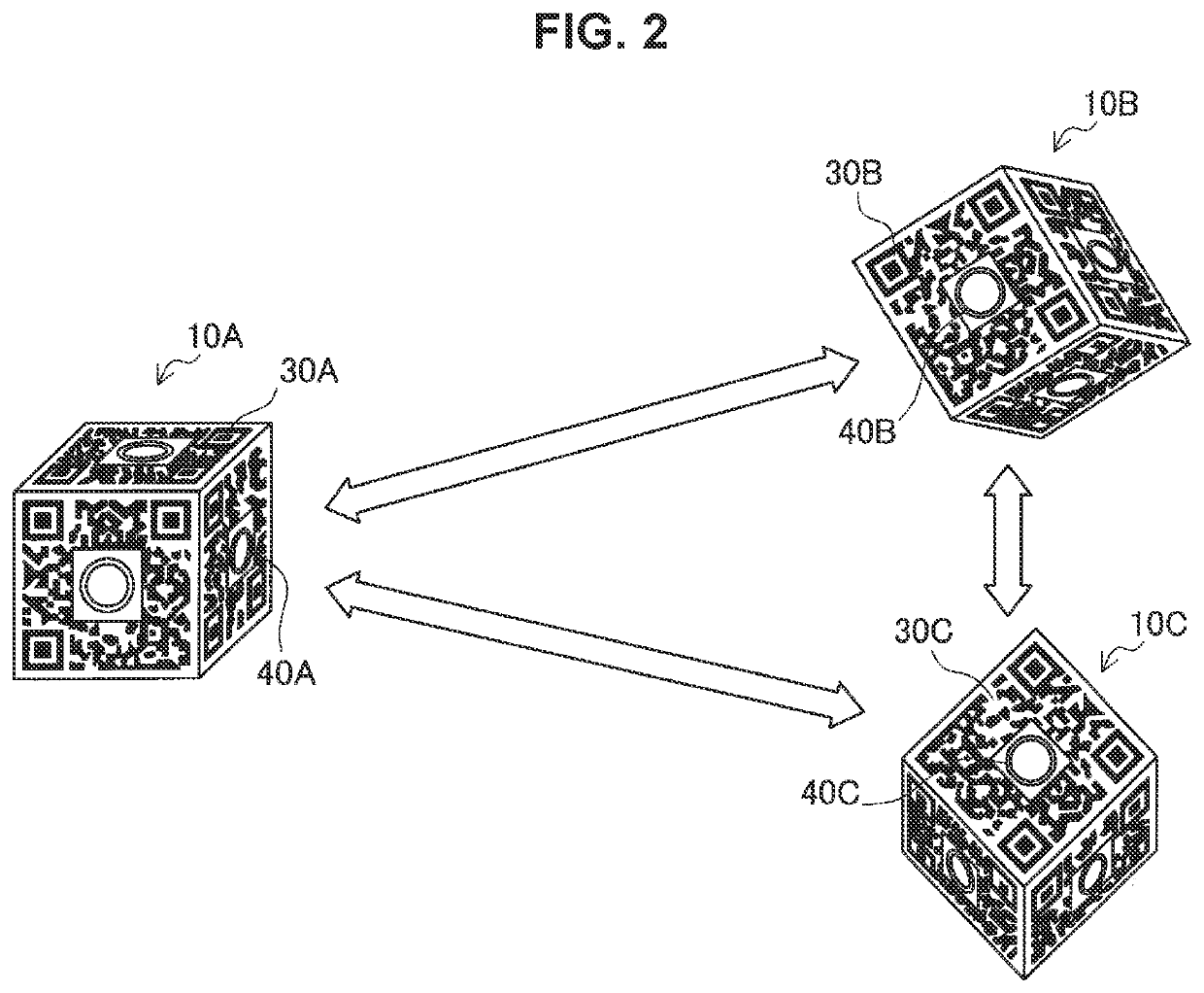
[0049]FIG. 1 is a diagram for describing an outline of a sensor system 1 according to the present embodiment. As illustrated in FIG. 1, the sensor system 1 includes a plurality of sensor devices 10 (that is, 10A to 10C) attached to a sensor attachment apparatus 20.

[0050]The sensor device 10 is a device that senses various kinds of data. The sensor device 10 is attached to a sensor attachment tool 21 included in the sensor attachment apparatus 20 to perform sensing targeting a move of a target object. A target object may be a human, a dog, a cat, or other living organisms, or may be a non-living organism such as a robot. In the example illustrated in FIG. 1, a target object is a user (that is, a human). In addition, the target object may be an object to be used by a living organism. For example, the target object may be a tool to be used for games such as a golf club, a tennis racket, a ski board, a ski boot, a goal, or a bat. In addition, the target object may be ...

second embodiment

3. Second Embodiment

[0104]The present embodiment is an embodiment in which computing based on sensor information is performed in an information processing device other than the sensor device. Here, description will be given as computing is performed in a server 80 to be described later.

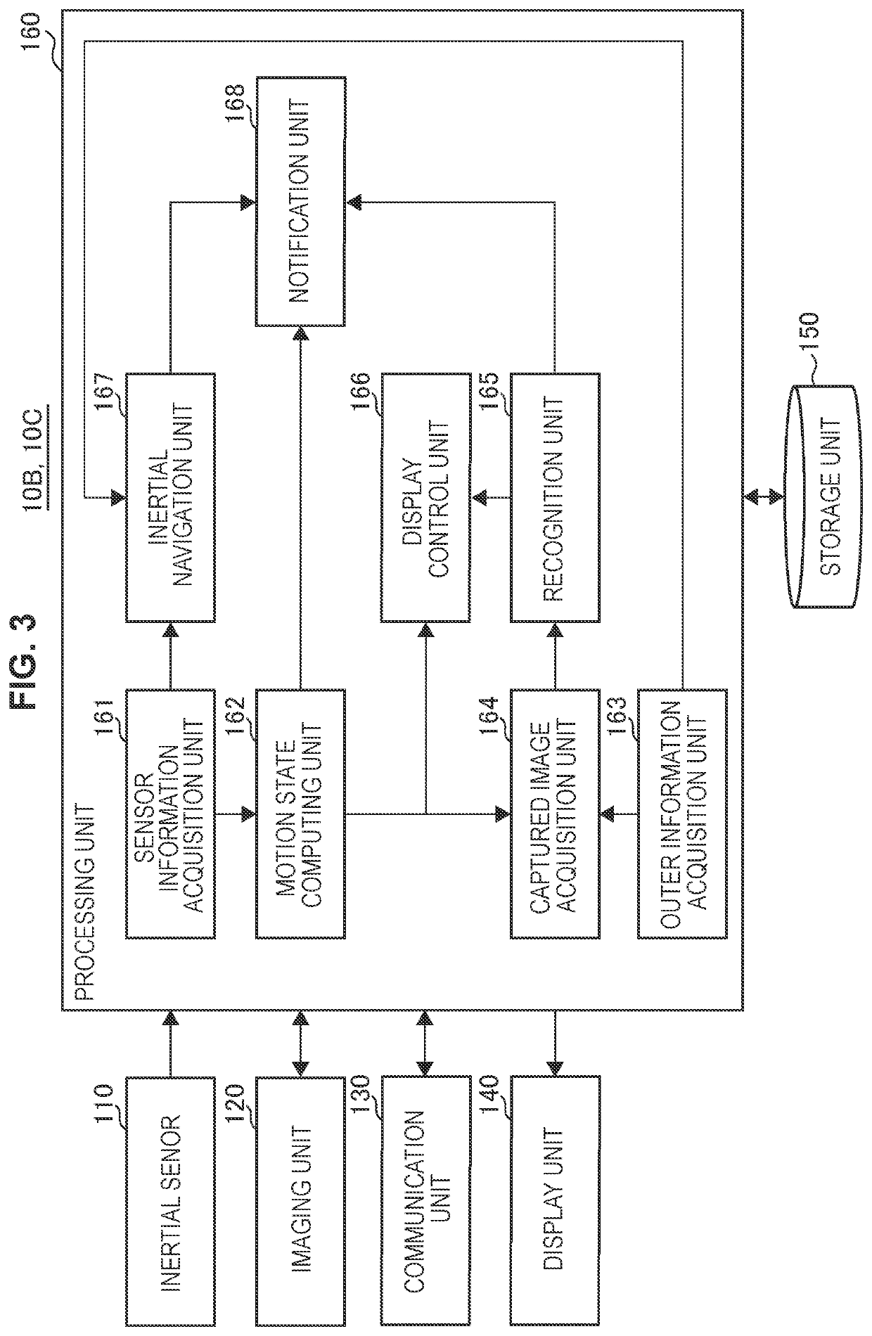
[0105]FIG. 10 is a block diagram illustrating an example of a logical configuration of the sensor device 10 according to the present embodiment. As illustrated in FIG. 10, the sensor device 10 includes the inertial sensor 110, the imaging unit 120, the communication unit 130, the display unit 140, the storage unit 150, and the processing unit 160.

[0106]The functions of the inertial sensor 110, the imaging unit 120, the communication unit 130, the display unit 140, and the storage unit 150 are as described in the first embodiment.

[0107]The processing unit 160 corresponds to a CPU, a DSP, or the like, and performs a process for providing various functions of the master 10. As illustrated in FIG. 10, the...


PUM


Abstract

There is provided a sensor device that can easily reduce an accumulated error in a sensor, the sensor device including: a first inertial sensor; a first information code formed to be capable of being imaged from an outside; and a first imaging unit capable of imaging a second information code formed on another sensor device.

Description

CROSS REFERENCE TO PRIOR APPLICATION[0001]This application is a National Stage Patent Application of PCT International Patent Application No. PCT / JP2016 / 071092 (filed on Jul. 15, 2016) under 35 U.S.C. § 371, which claims priority to Japanese Patent Application No. 2015-177603 (filed on Sep. 9, 2015), which are all hereby incorporated by reference in their entirety.TECHNICAL FIELD[0002]The present disclosure relates to a sensor device, a sensor system, and an information processing device.BACKGROUND ART[0003]Recently, technology to visualize (that is, to digitize) a move of a body has been actively developed. In the field of sports, for example, technology is being developed to attach sensor devices to various parts of a body for visualizing a move of the body on the basis of the measurement results and contributing to improvement in forms, and the like.[0004]For example. Patent Literature 1 below discloses technology that generates information regarding sports on the basis of sensor...

Claims


Application Information

Patent Timeline
Patent Type & Authority Patents(United States)
IPC IPC(8): G01P21/00G01B11/00G01C21/16G01B21/16G01B21/22G01P13/00
CPCG01P21/00G01B11/00G01B21/16G01B21/22G01C21/165G01P13/00G01C21/1656
Inventor YAMASHITA, KOSEIMURAKOSHI, SHOAOKI, SUGURU
Owner SONY CORP
Learn More