
Trajectory correction method and apparatus for k-space data in magnetic resonance imaging

a magnetic resonance imaging and trajectory correction technology, applied in the field of magnetic resonance imaging, can solve the problems of reducing the quality of the reconstructed mr image, introducing image artifacts, and shifting the data points in k-space, so as to reduce the calculation amount for trajectory correction and the complexity of calculation, reduce the accumulated errors, and increase the stability of the correction algorithm.

Active Publication Date: 2014-01-02
SIEMENS HEALTHCARE GMBH
View PDF2 Cites 2 Cited by
  • Summary
  • Abstract
  • Description
  • Claims
  • Application Information

AI Technical Summary

Benefits of technology

The invention provides a method for correcting the positions of data points in magnetic resonance imaging to reduce the calculation amount and complexity of the trajectory correction. The method divides k-space into a nonlinear region and a linear region and applies different techniques to perform positional correction on data points in each region. This reduces the accumulated errors resulting from a large-region correction calculation and improves the stability and image quality of the correction algorithm.

Problems solved by technology

Compared to Cartesian sequences, non-Cartesian sequences and fast imaging sequences are very sensitive to gradient delay and eddy currents, that will result in a positional shift of the data points in k-space.
If the shift between the actually obtained position of a data point and the desired filling trajectory of the data point is not corrected, then erroneous filling of k-space data will result, thus introducing image artifacts, and reducing the quality of the reconstructed MR image.
In the prior art, trajectory correction of data points in k-space is readily performed by calculating the desired trajectories of the data points of the entirety of k-space, which requires a significant amount of complicated calculations.
Moreover, since the calculated region is the entirety of k-space, accumulated errors resulting from large region correction calculation are also very large, which affects the image quality.

Method used


Image

  • Trajectory correction method and apparatus for k-space data in magnetic resonance imaging
  • Trajectory correction method and apparatus for k-space data in magnetic resonance imaging
  • Trajectory correction method and apparatus for k-space data in magnetic resonance imaging

Examples


Embodiment Construction

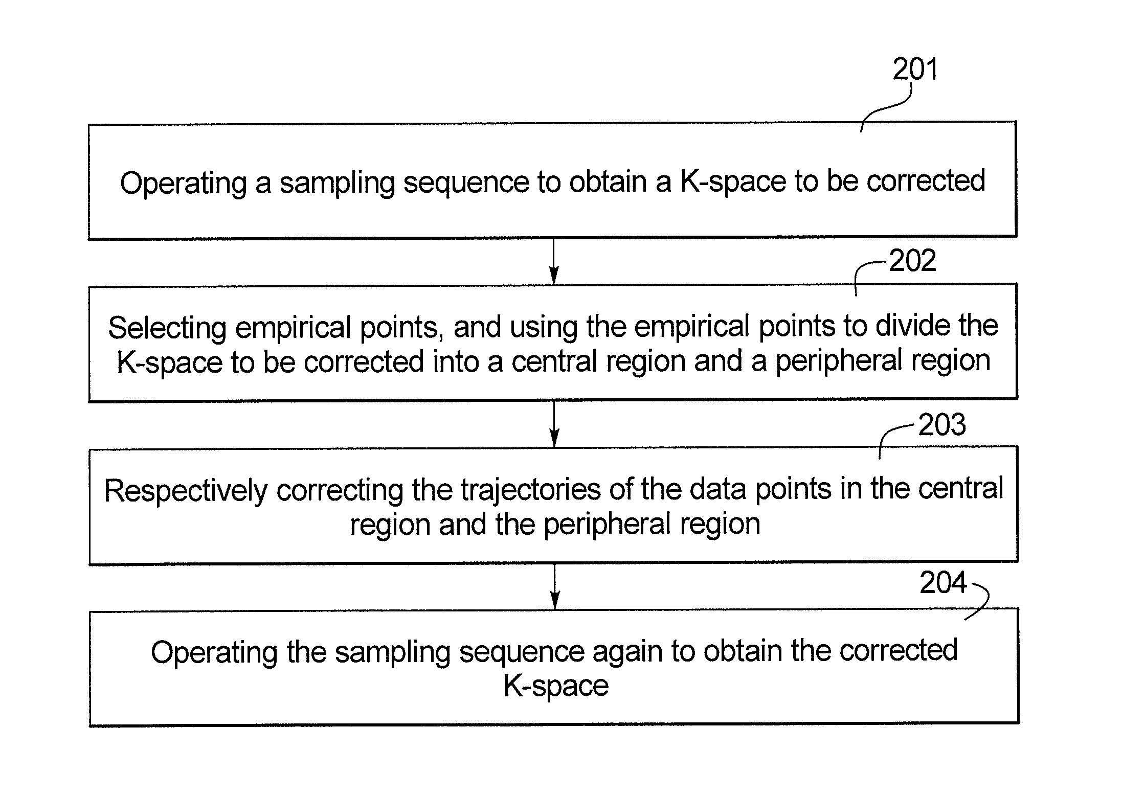
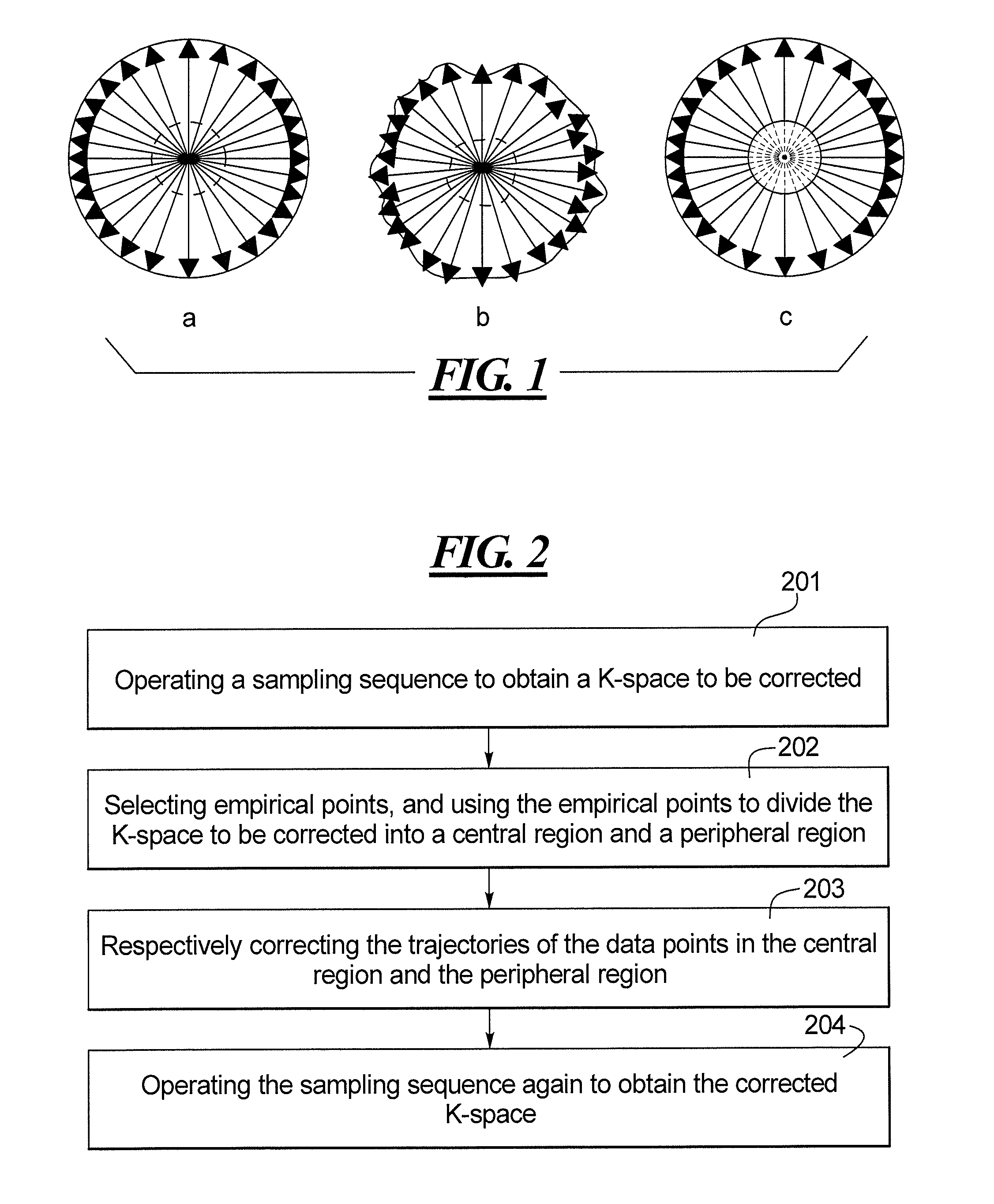
[0025]Shown in FIG. 1a is a schematic diagram of ideal k-space obtained by acquiring MR data to fill k-space according to a non-Cartesian sequence, e.g. a radial sequence. However, in actual operations, due to being affected by the electromagnetic effect resulting from eddy current, gradient changes will be prevented in each readout gradient (RO) direction, and therefore the filling (data entry) positions of the data points located in the central region (i.e. the region with a gradually increasing gradient magnitude) in k-space will be disordered; while in the peripheral region (i.e. the region of which the gradient magnitude is a constant) of k-space, even though the filling positions of the data points located in this region are not disordered. Due to being affected by the accumulated errors within the central region, the filling positions of the data points in the peripheral region will also shift, and therefore, the actually obtained k-space is shown as in FIG. 1b. The purpose o...


PUM


Abstract

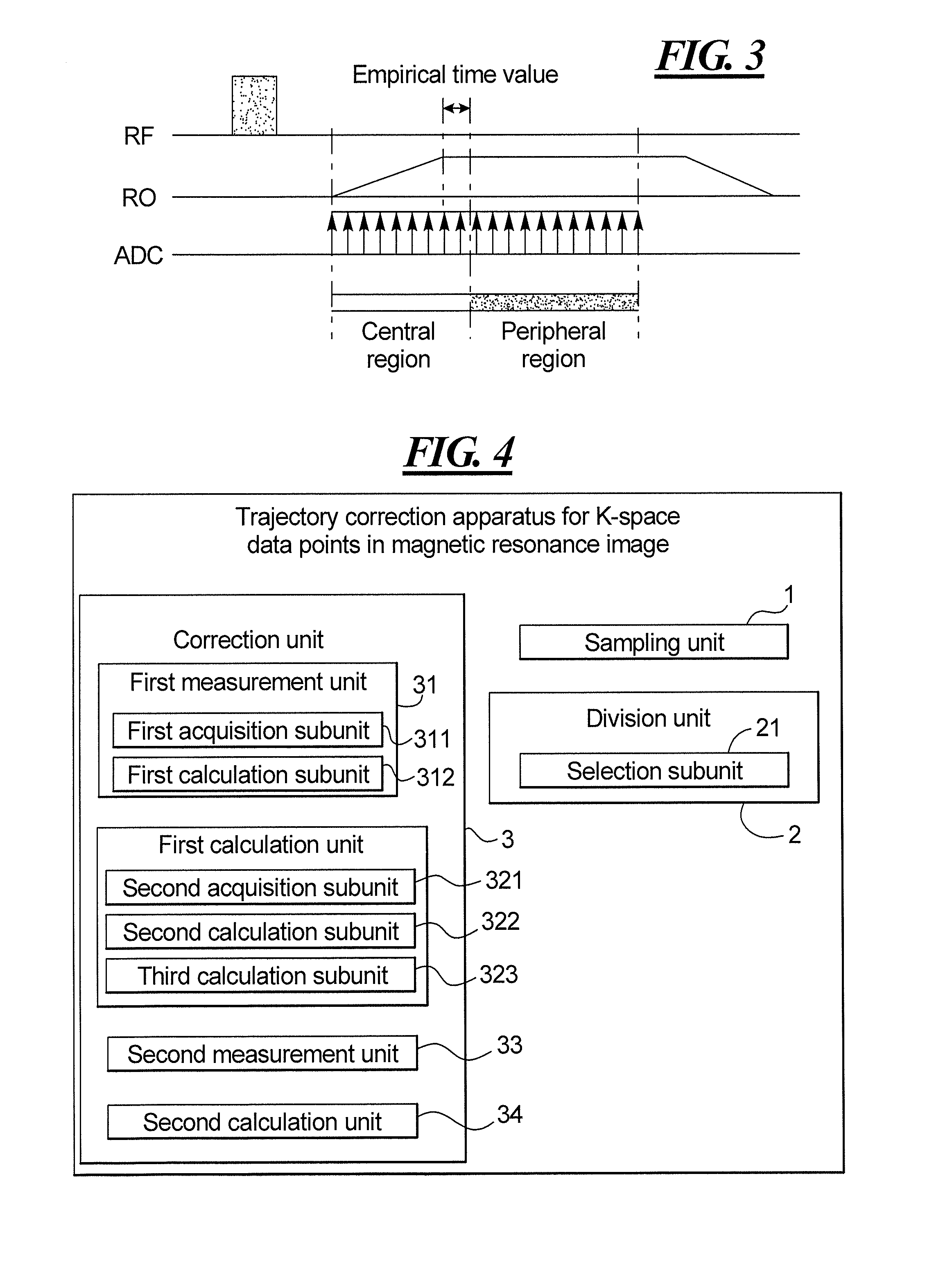
In a trajectory correction method and apparatus for k-space data points in magnetic resonance imaging, a magnetic resonance data acquisition unit is operated to execute a sampling sequence to obtain k-space to be corrected. Empirical points are selected used to divide k-space to be corrected into a central region and a peripheral region. The trajectories of the data points in the central region and the peripheral region are corrected and the sampling sequence is executed again, with the corrected trajectories, to obtain corrected k-space.

Description

BACKGROUND OF THE INVENTION[0001]1. Field of the Invention[0002]The present invention concerns magnetic resonance imaging, and in particular a trajectory correction method and apparatus for k-space data in magnetic resonance imaging.[0003]2. Description of the Prior Art[0004]The term spatial frequency refers to variations in frequency per unit of distance in a certain direction of a periodically changing physical parameter. The spatial frequency k is a space vector, and is usually used for describing certain energies that spread in space in the form of waves (such as various electromagnetic waves). Due to the vector properties of k, usually three vector components kx, ky, and kz, which are mutually perpendicular to each other, are used to represent k. These three vector components kx, ky, and kz correspond to a three-dimensional coordinate system, and the mathematical space or domain corresponding to the coordinate system determined by kx, ky, and kz is called k-space.[0005]In the f...

Claims


Application Information

Patent Timeline
Patent Type & Authority Applications(United States)
IPC IPC(8): G01R35/00G01R33/48
CPCG01R35/005G01R33/4822G01R33/482G01R33/4824G01R33/565
Inventor WENG, DE HEZHANG, QIONG
Owner SIEMENS HEALTHCARE GMBH
Learn More