A hydraulic end assembly of a plunger pump with a conical surface positioning sealing box body

A liquid end, plunger pump technology, applied to the components of the pumping device for elastic fluid, pump components, variable displacement pump components, etc., to reduce accumulation errors, reduce stress concentration points, and reduce accumulation effect of error

Active Publication Date: 2019-03-26
NINGBO HELI MECHANICAL PUMP CO LTD
View PDF7 Cites 0 Cited by
  • Summary
  • Abstract
  • Description
  • Claims
  • Application Information

AI Technical Summary

Problems solved by technology

But its shortcoming is that the sealing body still does not deviate from the installation method of the traditional liquid end structure, that is, the sealing body is installed on the plane of the pump body and fixed on the pump body with bolts. terminal fuselage positioning datum

Method used


Image

  • A hydraulic end assembly of a plunger pump with a conical surface positioning sealing box body
  • A hydraulic end assembly of a plunger pump with a conical surface positioning sealing box body
  • A hydraulic end assembly of a plunger pump with a conical surface positioning sealing box body

Examples


Embodiment Construction

[0028] The present invention will be further described in detail below in conjunction with the accompanying drawings and embodiments.

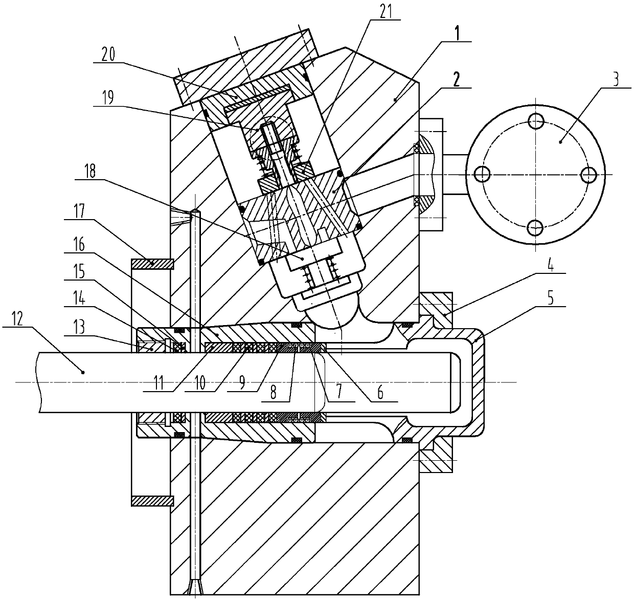
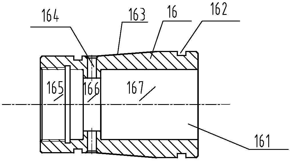
[0029] Please refer to Figure 1-Figure 3 As shown, the hydraulic end assembly of the conical surface positioning sealing body of the present invention mainly includes a pump body 1, a plunger 12, a sealing body 16, a combined valve 2, a packing assembly, an auxiliary packing 14, a water ring sleeve 5, Positioning sleeve 17 and water collector 3 etc., wherein:

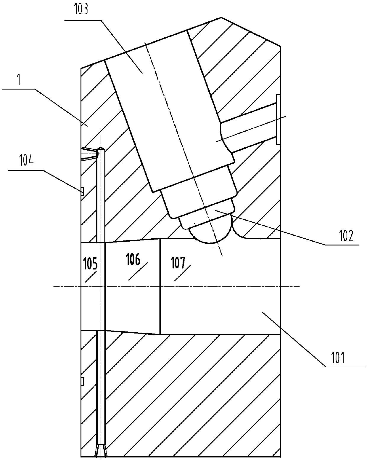
[0030] The cavity structure of the pump body 1 is as follows: figure 2 As shown, a plunger passage 101 and a combination valve passage 103 communicated with the plunger passage are provided inside. In this embodiment, the two passages have a V-shaped structure in which the center line forms a non-90-degree angle, so that the valves located in the combination valve passage Combination valve is oblique vertical linear movement. Of course, the arrangement of the two channels is not li...


PUM


Abstract

The invention relates to a plunger pump fluid end assembly of a cone-located sealed box body. The plunger pump fluid end assembly comprises a pump body, a plunger piston and a combination valve, wherein a plunger piston channel and a combination valve channel are formed in the pump body, the plunger piston is movably arranged in the plunger piston channel, the combination valve is arranged in the combination valve channel, a conical hole capable of accommodating the sealed box body is formed in the plunger piston channel, and the sealed box body is arranged in the plunger piston channel through a cone matched with a wall surface of the conical hole in a mode of capable of rotating in the radial direction; a filler assembly consisting of a pressing ring, main filler, a main guiding sleeve, a compensating spring and a spring seat is arranged in the sealed box body, and the plunger piston axially penetrates through the filler assembly. By means of forming the conical hole in the plunger piston channel, the sealed box body is arranged through a self-locking location effect of the conical hole; by means of the compensating spring which is arranged through inlet and outlet pressure of media and filler self sealing, the sealed box body is fixed in the plunger piston channel of the pump body, additional bolts for fixing the box body arranged on the pump body are avoided, and the length of a pump can be shortened by the size of the box body; furthermore, accumulated errors of parts are reduced, repeated assembly precision is improved, eccentric wear caused by the accumulated errors is reduced, and service life of quick-war parts is prolonged.

Description

technical field [0001] The invention relates to the technical field of plunger pumps, and more specifically relates to a hydraulic end assembly of a plunger pump that uses a tapered surface to position a sealing body. Background technique [0002] The structure of the liquid end of the traditional plunger pump is usually that the box body installed with packing is fixed on the pump body with bolts or steps, and the large outer diameter of the box body is positioned on the inner hole of the front facade of the fuselage to realize hydraulic pressure. The end plunger is parallel to the cross head of the power end to ensure a straight line during operation: 1. Straight-through type (up and down valves), see the attached Figure 4 ;2. Three-way type (inlet valve vertical type, liquid discharge valve horizontal type), see attached Figure 5 ; 3. Horizontal type (horizontal combination valve), see attached Figure 6 . Liquid ends of three different shapes and structures generally...

Claims


Application Information

Patent Timeline
Patent Type & Authority Patents(China)
IPC IPC(8): F04B53/02F04B53/10F04B53/22
CPCF04B53/02F04B53/109F04B53/22
Inventor 陈明海
Owner NINGBO HELI MECHANICAL PUMP CO LTD
Why Eureka
Try Eureka