
Protective suit

a protective suit and suit technology, applied in the field of personal protective equipment, can solve the problems of impeding the movement of wearers, affecting the safety of wearers, and individuals involved in potentially hazardous situations

Active Publication Date: 2021-04-20
PROD PASSAU INC
View PDF33 Cites 1 Cited by
  • Summary
  • Abstract
  • Description
  • Claims
  • Application Information

AI Technical Summary

Benefits of technology

The modular suit provides enhanced protection with improved mobility and temperature control, allowing for effective use in diverse environments and emergency situations.

Problems solved by technology

Individuals involved in potentially hazardous situations like one found during riots, public disturbances, manifestations, demonstrations, or protests are at risk of confrontation and attack from multiple sources and may therefore require body protection to prevent or mitigate injury-causing or life-threatening encounters or aggression.
In most instances, the design and construction of the protective suits are such that successive layers of protective material are placed at sensitive areas of the body, for example adjacent to body joints and articulations, which all together result in impeding wearer's movement.
Further, rigid material used in hardened inserts and shells that may be loosely attached on the outer layers of protective suits may also have a tendency to move or slide from their respective positioning to further hamper wearer's movement.
Moreover, these protective suits are not generally designed and built around the idea of body temperature control and consequently do not implement such features to facilitate breathability and air circulation through the various material layers.
This may prove challenging for the wearer in regions where the weather is hot.
On the other hand, not all the protective suits known in the art are readily configurable to adapt to the demanding environment and changing conditions that may be present on the field.

Method used


Image

  • Protective suit
  • Protective suit
  • Protective suit

Examples


Embodiment Construction

[0165]In the following description of the embodiments, references to the accompanying drawings are by way of illustration of an example by which the invention may be practiced. It will be understood that other embodiments may be made without departing from the scope of the invention disclosed.

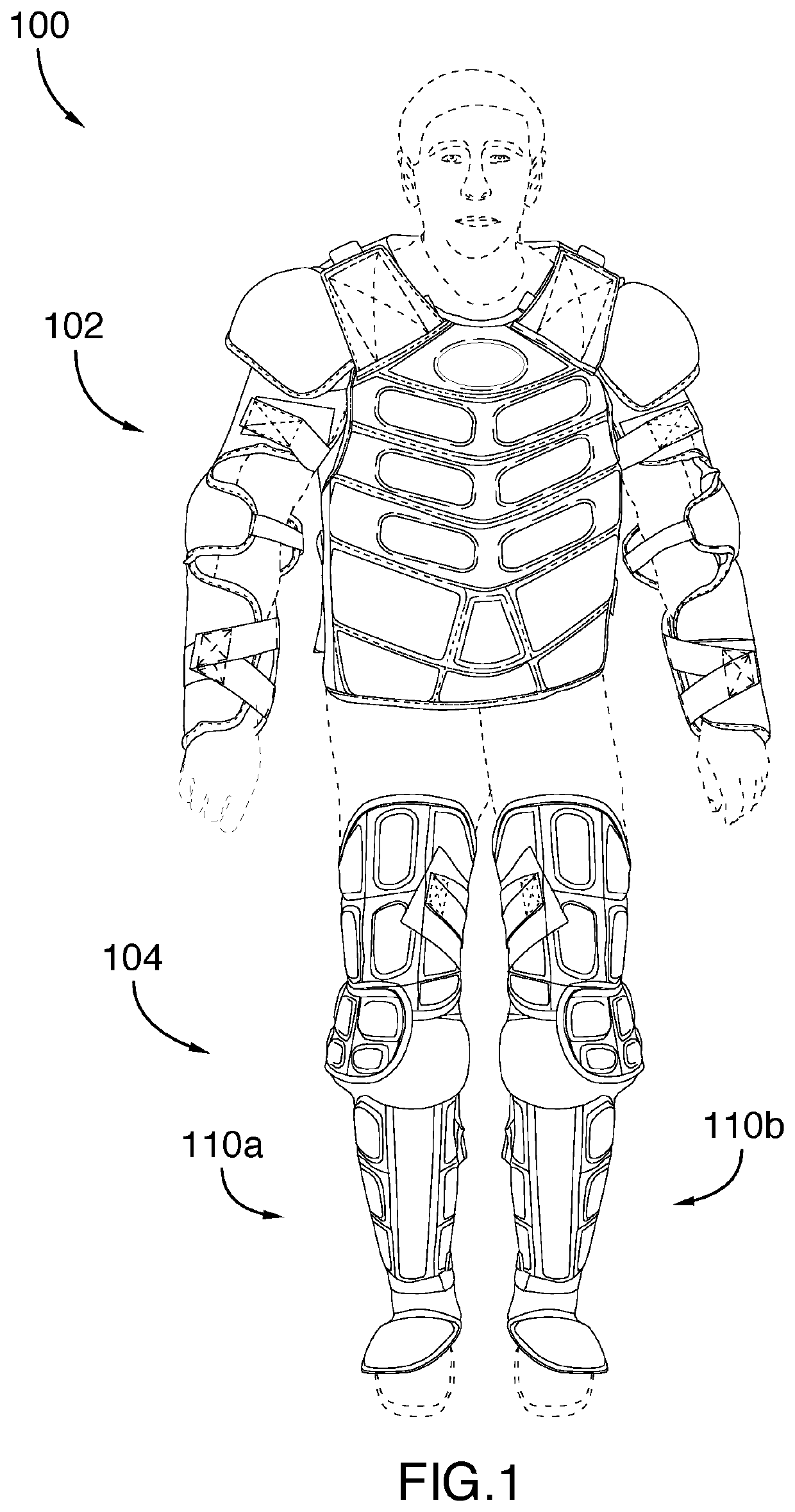
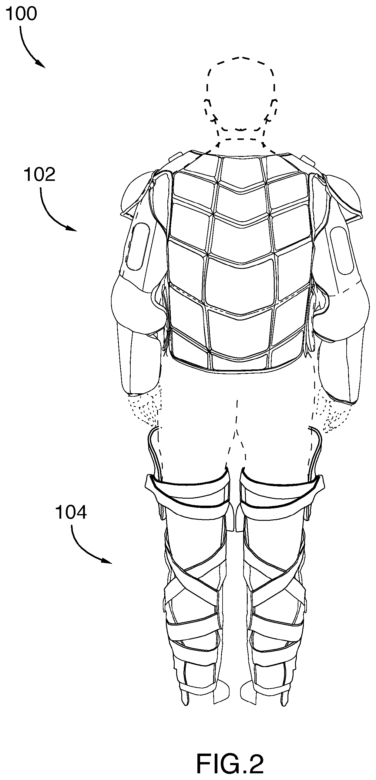
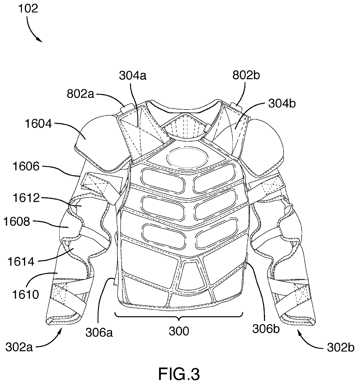
[0166]Referring to FIGS. 1 and 2, there is disclosed a protective suit 100 fitting various wearer's sizes and adapted for providing protection and freedom of movement. Accordingly, the protective suit 100 may be adjusted to conform to different wearer's anatomies and varying configuration preferences. The protective suit 100 may also include features like easy access to the wearer's torso (or trunk) (e.g. in case of emergency or to facilitate clothing), body temperature control, and modular anti-ballistic or bulletproof capabilities, for instance. In one embodiment, the protective suit 100 comprises an upper body assembly 102 and a lower body assembly 104. As it will be appreciated herein, the ...


PUM


Abstract

The present invention relates to a protective upper and lower body assemblies and protective suit comprising the same. The protective upper body assembly comprises a ventral and a dorsal padding panels, a left and a right shoulder fasteners, and a left and a right flank fasteners. Each of the ventral and the dorsal padding panels include at least two layers of resiliently compressible material and one layer of breathable material. The protective lower assembly comprises a left and a right upper thigh portions, a left and a right lower thigh portions, a left and a right knee shells, a left and a right lower leg portions, and a left and a right feet shells.

Description

TECHNICAL FIELD[0001]The invention relates to personal protective equipment, and more particularly to a protective suit comprising upper and lower body assemblies for protecting a wearer.BACKGROUND[0002]Individuals involved in potentially hazardous situations like one found during riots, public disturbances, manifestations, demonstrations, or protests are at risk of confrontation and attack from multiple sources and may therefore require body protection to prevent or mitigate injury-causing or life-threatening encounters or aggression. For example, direct force impact may be received through physical attack from hostile individuals (e.g. kicks, punches, and other bodily impacts) and objects wielded by such individuals (e.g. baseball bats, knives, and the like) or ballistic impacts may derive from various thrown objects, bullets, explosion fragments, and other projectiles.[0003]Most of the protective suits and other similar garments, gears, and equipment worn for body protection gene...

Claims


Application Information

Patent Timeline
Patent Type & Authority Patents(United States)
IPC IPC(8): A41D13/00A41D13/015
CPCA41D13/0153A41D13/0158A41D31/245A41D13/0156A41D27/28A41D13/065A41D13/08A41D13/0543A41D13/05A41D13/0512
Inventor BEAUDRY, HUGOBEAUDRY, ALAINLEMIEUX, ERIC
Owner PROD PASSAU INC
Learn More