Liquid pipe coupling universal joint and liquid product treatment device using the same

a technology of liquid pipe coupling and liquid product treatment device, which is applied in the direction of pipe joints, adjustable joints, mechanical devices, etc., can solve the problems of difficulty in achieving a smooth flow of indoor air, oil and fat contents contained in contaminated air continually colliding with a convex portion, etc., to achieve simple and easy configuration, improve the effect of pipe length and straight pipe portion

Active Publication Date: 2021-04-20
FKS
View PDF31 Cites 1 Cited by
  • Summary
  • Abstract
  • Description
  • Claims
  • Application Information

AI Technical Summary

Benefits of technology

[0037]The liquid pipe coupling universal joint used as a liquid channel according to the present invention employs the basic technical configuration described above. As a result, the liquid pipe coupling universal joint has a simple and easy configuration, and a connection adjustment work between a plurality of connected pipes, that is, the straight pipe portions becomes significantly easy. Meanwhile, since an uneven obstacle is not provided on the inner surface of the connected portion between the straight pipe portions, in particular, on the inner surface of the lower end, a flow of gas or liquid is not hindered. Furthermore, using the liquid channel universal pipe joint according to the present invention, it is possible to change the angle in an extremely wide range in operation for adjusting the setting angle required between both straight pipe portions in a connection portion of at least two continuous straight pipe portions. Meanwhile, it is possible to easily execute a precise angle setting or angle adjustment operation in each portion and freely and individually change and adjust diameters of the connected straight pipe portions. Therefore, it is possible to easily and rapidly execute necessary pipe slope setting operation in a limited narrow pipe passage space and thus remarkably reduce cost for the pipe mounting work. In particular, it is not necessary to perform a pipe cleaning work using a high-pressure cleaning system that has been required to perform at least once a year. Therefore, it is possible to remarkably reduce a maintenance cost for a long time.
[0038]In the liquid pipe coupling universal joint according to the present invention, the straight pipe portions are designed by combining the essential requirements described above, such that pivoting and direction change can be performed in a semi-omnidirectional manner, and the overlapping area between the spherical portions of the first and second fitting portions increases. Therefore, liquid pipe coupling universal joint according to the present invention also has a high strength for a vibration or an external impact and absorbs a vibration or an impact. Accordingly, since the liquid pipe coupling universal joint according to the present invention has excellent durability for an earthquake or an impact such as explosion, it is possible to obtain a liquid pipe coupling universal joint having excellent earthquake resistance or vibration resistance. This significantly can contribute to a long-term conservation effect.
[0039]If at least two liquid pipe coupling universal joints according to the present invention are combined in a single line, a free swing capability between the straight pipe portions of the universal joint is applied. Therefore, it is possible to obtain an earthquake resistance effect or a vibration resistance effect.

Problems solved by technology

However, since the elbow pipe is a pipe joint having a fixed bent angle of 90° or the like, this is a difficult work due to decentering (decentering angle) of the coupling direction, and the work may not be appropriately performed only using a single elbow pipe.
However, since the bellows pipe has minute unevenness on its inner surface, flow resistance increases, and it is difficult to achieve a smooth flow of the indoor air.
In particular, if the bellows pipe is employed as an external pipe for a range hood that discharges the contaminated air generated during cooking to the outdoor, oil and fat contents contained in the contaminated air continually collide with a convex portion of the minute unevenness, so that oil and fat contents may be piled in the pipe.
This is undesirable in terms of fire prevention.
However, the pipe mount space is typically limited to a very narrow passage in order to reduce a construction cost.
However, although elbow pipes are produced from many manufacturers, a bending angle of such an elbow pipe is limited to a particular angle predetermined by manufacturers, such as 45°, 75°, 90°, and 180°.
Therefore, it is difficult to set the curved angle of the coupled pipes to a certain angle even by combining various types of elbow pipes.
Furthermore, even when a user tries to obtain a predetermined curved angle by combining a plurality of elbow pipes, a significant space is necessary around a pipe group including the elbow pipe in such a coupling portion.
Therefore, it is difficult to substantially set a predetermined slope or angle by combining a plurality of elbow pipes inside the narrow pipe layer set in advance.
However, in such a bendable elbow pipe joint, a connectable bending angle between a pair of straight pipes is limited to a small range of about 10° to 20°.
Therefore, such a bendable elbow pipe is not substantially usable in practice.
Therefore, in the background art, it is nearly impossible to implement a predefined slope according to the building construction standards in all pipe layers.
Therefore, it is difficult to set a predetermined slope of the liquid pipe in many portions.
Accordingly, a maintenance cost increases disadvantageously.
In appearance, this may be seen as the piping complies with the relating regulations regarding the slope, and such cheating occurs frequently.
For such an unlawful piping work, naturally, sludge may remain in the pipe, or an excessive load may be continually applied to the pipe for a long time.
Therefore, durability of a pipe system is remarkably degraded, and this becomes a social issue.
Such a problem also occurs in a plurality of connection portions provided in a plurality of pipes extending from a subterranean part of the detached housing or a high-rise housing to the sewerage main manhole.
Furthermore, in the connection portion of the pipe using an elbow pipe of the background art, the elbow pipe portion and the straight pipe portion fastened to the elbow pipe are just simply fitted, and do not have flexibility, so that a coupling strength is low.
If a large vibration such as an earthquake is applied, the fitting portion between the elbow pipe and the straight pipe may be broken or removed from each other.
In some cases, necessary gases or liquids may leak, so that a secondary disaster may occur dangerously.
Therefore, it is difficult to sufficiently absorb a vibration such as an earthquake, and vibration resistance performance is unsatisfactory, so that the articulation assembly may be broken disadvantageously.
In this configuration, it is impossible to provide sufficient freedom in a bending angle between least two straight pipe portions to be connected, and the universal joint is used only as a connection joint in a very small part.
Therefore, practicality is short in reality.
Therefore, Patent Literature 2 fails to satisfy an enablement requirement.
Therefore, in this state of the description, it is difficult to specify an arrangement position and an arrangement shape of the reference plane.
Accordingly, Patent Literature 2 fails to serve as an effective disclosure for any later technique.
Therefore, even a person ordinarily skilled in the art would be impossible to manufacture the universal joint in an industrial sense from the technique of Patent Literature 2.
In other words, Patent Literature 2 fails to discuss or suggest a novel and inventive technique concept capable of addressing the aforementioned problems of the background art.
Therefore, it is difficult to say that an overlappingly fitting portion between the opening edge of the outer spherical body and the opening edge of the inner spherical body has an area or a length remarkably larger than those of the background art.
Accordingly, there is no description regarding a fact that the bending angle formed by a pair of connected straight portions increases compared to the background art, and it is difficult to guarantee such a fact.
In addition, it is inevitable to think that the coupling portion may be highly possibly disassembled or damaged by a vibration such as an earthquake.
That is, both Patent Literatures 1 and 2 fail to perfectly disclose or suggest necessary technical information for addressing problems of the background art.
However, a ratio of the outer sphere covering the inner sphere is extremely large, and a variable angle range between the straight pipe portions is significantly small.
Therefore, practicality is short.
Therefore, it is difficult to perform such manual operation in a construction site, and work efficiency is significantly degraded.
Furthermore, since fluid stays inside, practicality is short.

Method used


Image

  • Liquid pipe coupling universal joint and liquid product treatment device using the same
  • Liquid pipe coupling universal joint and liquid product treatment device using the same
  • Liquid pipe coupling universal joint and liquid product treatment device using the same

Examples


Embodiment Construction

[0082]A configuration of a liquid pipe coupling universal joint according to the present invention will now be described in details with reference to the accompanying drawings.

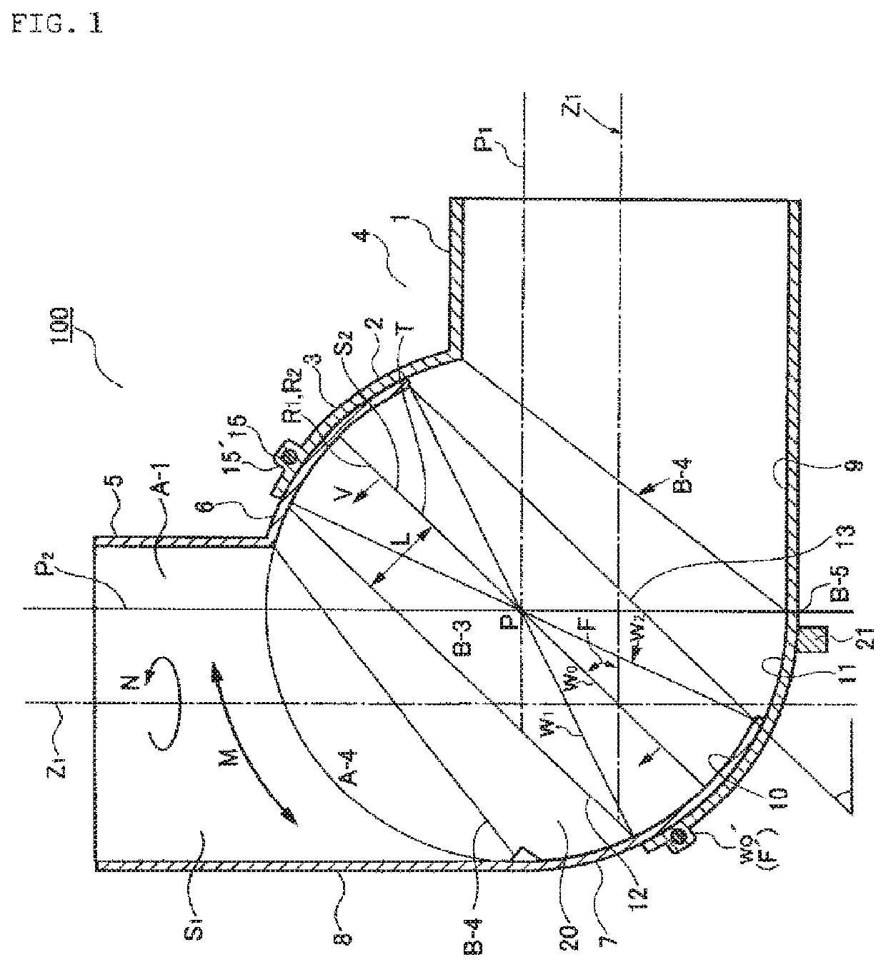
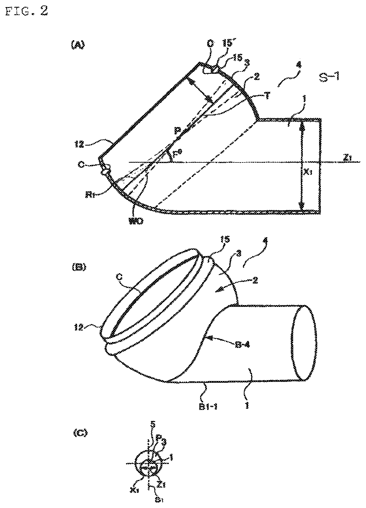
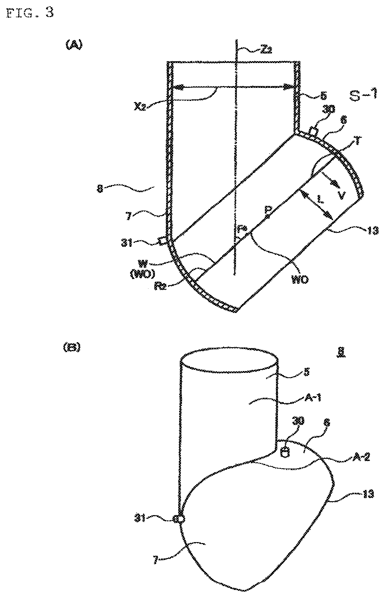
[0083]Specifically, FIG. 1 is a diagram illustrating a basic structure of the liquid pipe coupling universal joint 100 according to an embodiment of the present invention for showing an embodiment of a basic technical concept. Referring to FIG. 1, a universal joint 100 used in a pipe coupling portion includes: a first coupling structure 4 having a first straight pipe portion 1 and a first fitting portion 3 as a curved body 2 that forms a part of a spherical body connected to one end of the first straight pipe portion 1; and a second coupling structure 8 having a second straight pipe portion 5 and a second fitting portion 7 as a curved body 6 that forms a part of a spherical body connected to one end of the second straight pipe portion 5, wherein any one of the first and second fitting portions 3 and 7 has a di...


PUM


Abstract

A pipe coupling universal joint has a first fitting portion and a second fitting portion. An edge circumference of the first or second fitting portion is separated from a reference plane by a length set to 21 to 23% of the maximum diameter length of the first or second fitting portion on the reference plane in a direction opposite to a side where a straight pipe portion is connected from the reference plane.

Description

[0001]This is a National Phase Application filed under 35 U.S.C. § 371, of International Application No. PCT / JP2015 / 074557, filed Aug. 25, 2015.TECHNICAL FIELD[0002]The present invention relates a liquid pipe universal pipe joint used to connect various pipes used as a liquid channel, and more particularly, to a liquid pipe coupling universal joint and a liquid product treatment device using the same, capable of easily adjusting a precise setting angle required in various coupling portions of pipes serving as passages for various liquid flows and providing a high coupling strength, excellent earthquake resistance, and excellent vibration resistance.BACKGROUND ART[0003]In the background art, as an indoor ventilation system, there are known a wall surface direct-mount type directly mounted to a wall of a building by preparing an opening on the wall and a built-in type mounted to an inner side of a ceiling or a wall. Recently, the built-in type is prevailed. In this built-in type venti...

Claims


Application Information

Patent Timeline
Patent Type & Authority Patents(United States)
IPC IPC(8): F16L27/06F16L27/04
CPCF16L27/06F16L27/04F16L27/042
Inventor FUJIWARA, YASUTATSU
Owner FKS
Why Eureka
Try Eureka