Radio-over-fiber link device using multi-mode fiber and method of setting signal band thereof

a radio-over-fiber link and multi-mode fiber technology, applied in the direction of fiber transmission, multi-mode transmission, electrical apparatus, etc., can solve the problems of inefficient configuration of the remote antenna link for all services, difficulty in simultaneously receiving various service signals in only a narrow bandwidth of the mmf, and large reduction of coupling efficiency in the connection with a light emitting or receiving element. , to achieve the effect of convenient and simple configuration

Inactive Publication Date: 2007-06-21
SAMSUNG ELECTRONICS CO LTD
View PDF1 Cites 1 Cited by
  • Summary
  • Abstract
  • Description
  • Claims
  • Application Information

AI Technical Summary

Benefits of technology

[0010] Accordingly, the present invention has been made to solve the above-mentioned problems occurring in the prior art and provides additional advantages, by providing an ROF link device using an MMF for simultaneously receiving various wireless services effectively with an easy and simple configuration in a case where an ROF link is configured using the MMF, and a method of setting a signal band of the ROF link device.

Problems solved by technology

At this time, it is inefficient to configure a remote antenna link for all services in an environment in which there are provided various wireless services for voice, broadcasting, data and the like.
However, coupling efficiency is greatly lowered in a connection with a light emitting or receiving element due to a small core radius of the SMF.
However, in this case, there is a difficulty in simultaneously receiving various service signals in only a narrow bandwidth of the MMF.

Method used


Image

  • Radio-over-fiber link device using multi-mode fiber and method of setting signal band thereof
  • Radio-over-fiber link device using multi-mode fiber and method of setting signal band thereof
  • Radio-over-fiber link device using multi-mode fiber and method of setting signal band thereof

Examples


Embodiment Construction

[0023] Hereinafter, embodiments of the present invention will be described with reference to the accompanying drawings. In the following description, the same elements will be designated by the same reference numerals although they are shown in different drawings. For the purposes of clarity and simplicity, a detailed description of known functions and configurations incorporated herein will be omitted as it may make the subject matter of the present invention rather unclear.

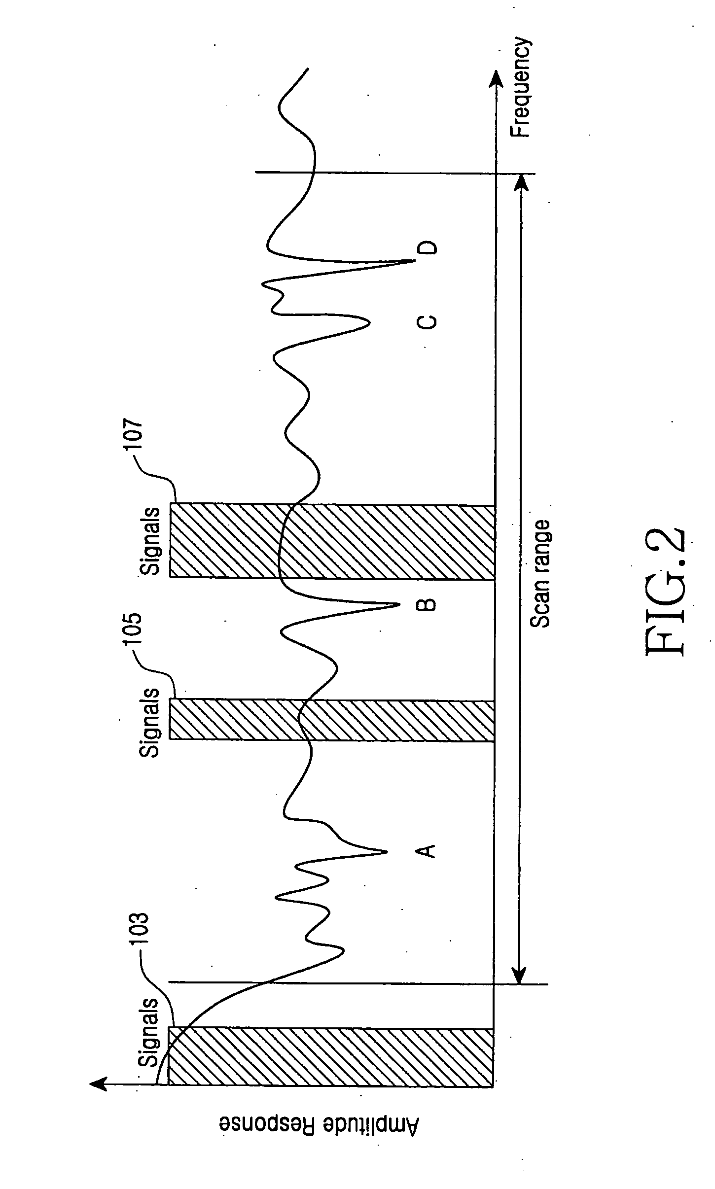
[0024]FIG. 2 is a graph of an exemplary frequency characteristic of a Multi-Mode Fiber (MMF), in which signal transmittable bands, 103, 105, 107 are displayed. Referring to FIG. 2, since the bandwidth of the MMF is too narrow to simultaneously receive several services using only an existing band 103 when the MMF is used, and in order to use a region larger than an existing bandwidth, regions outside the conventional bandwidth 103 may be identified and used in signal transmission.

[0025] That is, in a case of a ...


PUM


Abstract

Disclosed is a method of setting a signal band of a Radio-Over-Fiber (ROF) link device using a Multi-Mode Fiber (MMF), which includes the steps of dividing a preset band of the entire frequency band of the MMF as a plurality of frequency slots to preset a transmission band in a transmitting side device, sequentially sweeping a plurality of reference frequencies predetermined for each transmission band of the plurality of the frequency slots to only the bands of the corresponding frequency slots, identifying the possibility of signal transmission for each of the plurality of frequency slots in accordance with transmission quality information transmitted from a receiving side to set a transmission signal band, detecting the quality of a signal received for the corresponding frequency slot when sweeping a frequency for each of the plurality of frequency slots in the receiving side device, and transmitting the transmission quality information to the transmitting side device in accordance with the detected signal quality.

Description

CLAIM OF PRIORITY [0001] This application claims the benefit of the earlier filing date, pursuant to 35 USC 119, to that patent application entitled “Radio-Over-Fiber Link Device Using Multi-Mode Fiber and Method of Setting Signal Band Thereof” filed with the Korean Intellectual Property Office on Dec. 15, 2005 and assigned Serial No. 2005-124118, the contents of which are incorporated herein by reference. BACKGROUND OF THE INVENTION [0002] 1. Field of the Invention [0003] The present invention relates to a link device for processing various service signals through a multi-mode fiber and a method of setting a signal transmission band of the link device. [0004] 2. Description of the Related Art [0005] There has been an increasing necessity to provide high-speed wireless multimedia communication services by combining optical and radio communication technologies due to the diversification and rapid increase of information communication services. Accordingly, interest in technology for ...

Claims


Application Information

Patent Timeline
Patent Type & Authority Applications(United States)
IPC IPC(8): H04B10/00H04B10/2581
CPCH04B10/25752H04B10/2581H04B10/25H04B10/2575
Inventor KIM, SUNG-KEEKIM, HOONLEE, HAN-LIMHWANG, SEONG-TAEK
Owner SAMSUNG ELECTRONICS CO LTD
Why Eureka
Try Eureka