
Actuator

a technology of actuators and actuators, applied in the field of actuators, can solve the problem that the actuator cannot be simple, and achieve the effect of stable waterproofness

Active Publication Date: 2016-12-27
TOYODA GOSEI CO LTD
View PDF2 Cites 0 Cited by
  • Summary
  • Abstract
  • Description
  • Claims
  • Application Information

AI Technical Summary

Benefits of technology

[0008]The invention has been made to solve the problem, and an object thereof is to provide an actuator which can ensure the waterproofness and the prevention of the extension thereof before actuation with a simple and easy configuration, even in the event that a gas generator is used which generates operation gas when actuated.
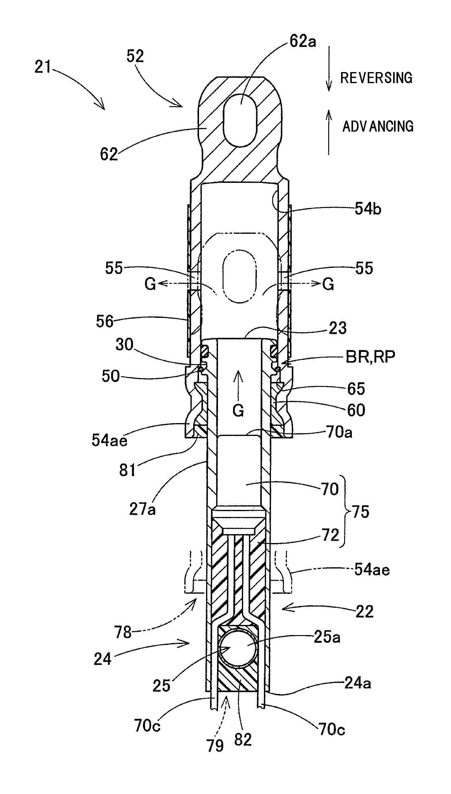
[0010]In the actuator according to the invention, since the seal material which doubles as the adhesive closes the gap (the seal portion) between the push-side portion and the accommodation-side portion, the intrusion of rain water into the gas generator can be prevented to thereby ensure the waterproofness of the actuator before actuation. In addition, before actuation, the seal material which doubles as the adhesive joins the push-side portion and the accommodation-side portion together at the seal portion, whereby the push-side portion can be restricted from advancing relative to the accommodation-side portion, and the extension of the actuator before actuation can be prevented. Additionally, since the seal material which doubles as the adhesive joins the push-side portion and the accommodation-side portion together with the joining force which enables the push-side portion to move relative to the accommodation-side portion when actuated, the push-side portion releases the adhesion to move smoothly relative to the accommodation-side portion at the time of actuation of the actuator where the operation gas is generated from the gas generator.
[0011]In the actuator according to the invention, the seal material which doubles as the adhesive is provided by being poured and set through molding, and the seal material can easily be provided by being poured to fill the seal portion which is disposed on the external surface of the actuator. Further, in the actuator according to the invention, although the mold and the filling machine are needed, the conventionally required labor-hours to design to provide the packing, the packing accommodation groove, the E ring and the E ring accommodation groove or to assemble them together are unnecessary, and therefore, the actuator can be formed in a simple and easy fashion.
[0012]Consequently, in the actuator according to the invention, although the configuration is adopted in which the gas generator is used which generates the operation gas when actuated, the waterproofness and the prevention of the extension of the actuator before actuation can be ensured in a simple and easy fashion.
[0014]In the configuration like this, in pouring the seal material to fill the gap defined between the push-side portion and the accommodation-side portion, the seal material can simultaneously be poured to fill the space around the circumference of the input member in the accommodation-side portion. Because of this, in the configuration like this, the stable waterproofness of the whole of the actuator including the waterproofness around the circumference of the input member can easily be ensured.

Problems solved by technology

In addition, the E ring and the E ring accommodation groove also need to be provided, resulting in the problem that the actuator cannot be configured simple.

Method used


Image

  • Actuator
  • Actuator
  • Actuator

Examples


first embodiment

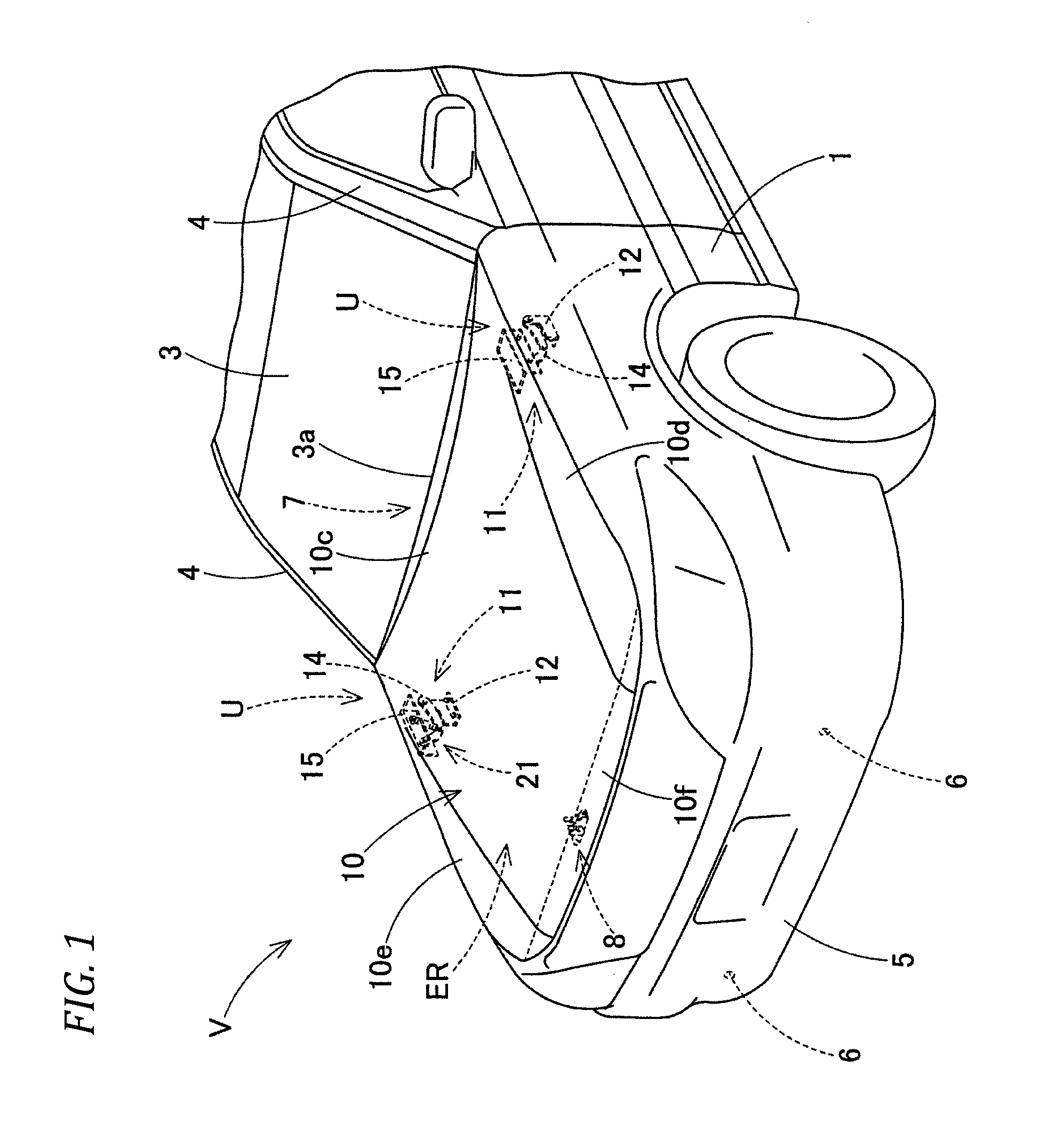
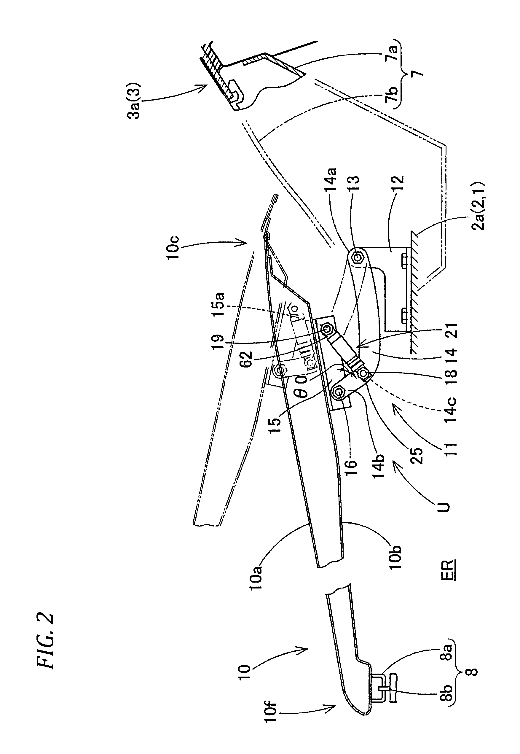
[0027]Hereinafter, an embodiment of the invention will be described based on drawings. As shown in FIGS. 1 to 3, an actuator 21 of a first embodiment is used in a hood pop-up apparatus (hereinafter, also referred to as a “pop-up apparatus” as required) U as an automotive safety apparatus and is provided in a hinge mechanism 11 near a rear end 10c of a hood panel 10 of a vehicle V.

[0028]In this specification, unless described otherwise, front-to-rear and up-to-down directions coincide with front-to-rear and up-to-down directions of the vehicle V (refer to FIG. 1), and a left-to-right direction coincides with a left-to-right direction of the vehicle V when looking at the front of the vehicle V from the inside thereof.

[0029]In the case of the first embodiment, sensors 6 are provided in a front bumper 5 of the vehicle V as shown in FIG. 1 to detect or predict a collision with a pedestrian, and signals from the sensors 6 are inputted into a control circuit, not shown. When the control un...

second embodiment

[0071]However, in the second embodiment, the actuator 121 is of a cylinder type, and an accommodation-side portion 122 includes a bottom wall portion 127 which accommodates and holds a gas generator 185, a ceiling wall portion 123 which is provided so as to face the bottom wall portion 127, and a cylindrical circumferential wall portion 126 which extends from an outer circumferential edge of the bottom wall portion 127 to the ceiling wall portion 123. A piston portion 153 of a push-side portion (a movable-side portion) 152 is made to slide on an inner circumferential surface 126a of the circumferential wall portion 126.

[0072]The push-side portion (the movable-side portion) 152 is configured as a piston rod having the piston portion 153 which slides on the inner circumferential surface 126a of the circumferential wall portion 126 and a rod portion 155 which extends from the piston portion 153 to project from an insertion hole 124 of the ceiling wall portion 123.

[0073]The piston rod (...


PUM

PropertyMeasurementUnit
melting temperatureaaaaaaaaaa
inclination angleaaaaaaaaaa

Abstract

An actuator includes: a gas generator which generates an operation gas when actuated; an accommodation-side portion which accommodates and holds the gas generator; and a push-side portion which is pushed by the operation gas generated from the gas generator to advance relatively so as to move away from the accommodation-side portion, wherein: a seal material which realizes watertightness between the push-side portion and the accommodation-side portion before actuation is provided in an external surface side portion between the push-side portion and the accommodation-side portion by being poured and set through molding; and the seal material doubles as an adhesive which enables the push-side portion to move relatively when actuated and which provides a joining force with which the push-side portion can be restricted from moving relatively before actuation so as to join the push-side portion and the accommodation-side portion together.

Description

CROSS-REFERENCE TO RELATED APPLICATION(S)[0001]This application is based upon and claims the benefit of priority from Japanese Patent Application No. 2014-217637, filed on Oct. 24, 2014, the entire contents of which are incorporated herein by reference.BACKGROUND[0002]1. Field of the Invention[0003]The present invention relates to an actuator which starts an operation of a device to which it is attached by generating an operation gas which is a combustion gas when activated and more particularly to, for example, an actuator which is preferably used for an onboard automotive safety apparatus such as a hood pop-up apparatus which lifts up a hood panel in receiving a pedestrian as a protection target.[0004]2. Description of the Related Art[0005]Some of conventional actuators like the one described above are used in a hood pop-up device which lifts up a hood panel, and those actuators are configured as a piston-cylinder type actuator which makes use of combustion gas generated as a resu...

Claims


Application Information

Patent Timeline
Patent Type & Authority Patents(United States)
IPC IPC(8): C06D5/00B60R21/38B60R21/00
CPCB60R21/38B60R2021/0004
Inventor TAKAYA, HISASHIKITTE, HAJIMESHIGETA, KOSUKE
Owner TOYODA GOSEI CO LTD
Learn More