Handling compensation for losses in optical fiber links

a technology of optical fiber and compensation, applied in the field of optical network systems and methods, can solve the problems of fiber loss and more attenuation

Active Publication Date: 2021-04-20
CIENA
View PDF36 Cites 2 Cited by
  • Summary
  • Abstract
  • Description
  • Claims
  • Application Information

AI Technical Summary

Benefits of technology

[0005]According to one embodiment of the present disclosure, a local controller may include a processing device and a memory device configured to store a computer program which may include a loss compensation module. The loss compensation module of the computer program may have instructions that, when executed, enable the processing device to measure accumulated losses over a fiber link. The instructions may further enable the processing device to at least partially compensate for the measured accumulated losses. In response to determining that there is a compensation shortfall with respect to the accumulated losses, the processing device may be configured to transmit the compensation shortfall to one or more downstream controllers, which, for example, may allow for compensation by a later amplification stage of a photonic line system.

Problems solved by technology

The additional fiber loss may be the result of a physically distressed fiber, such as a fiber pinch or other condition that might cause the fiber to experience more attenuation than a baseline level that might be based on the length of the fiber link.

Method used


Image

  • Handling compensation for losses in optical fiber links
  • Handling compensation for losses in optical fiber links
  • Handling compensation for losses in optical fiber links

Examples


Embodiment Construction

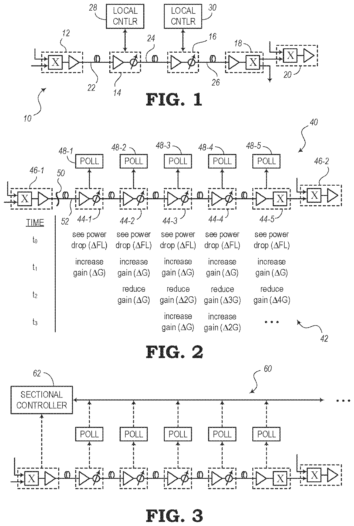
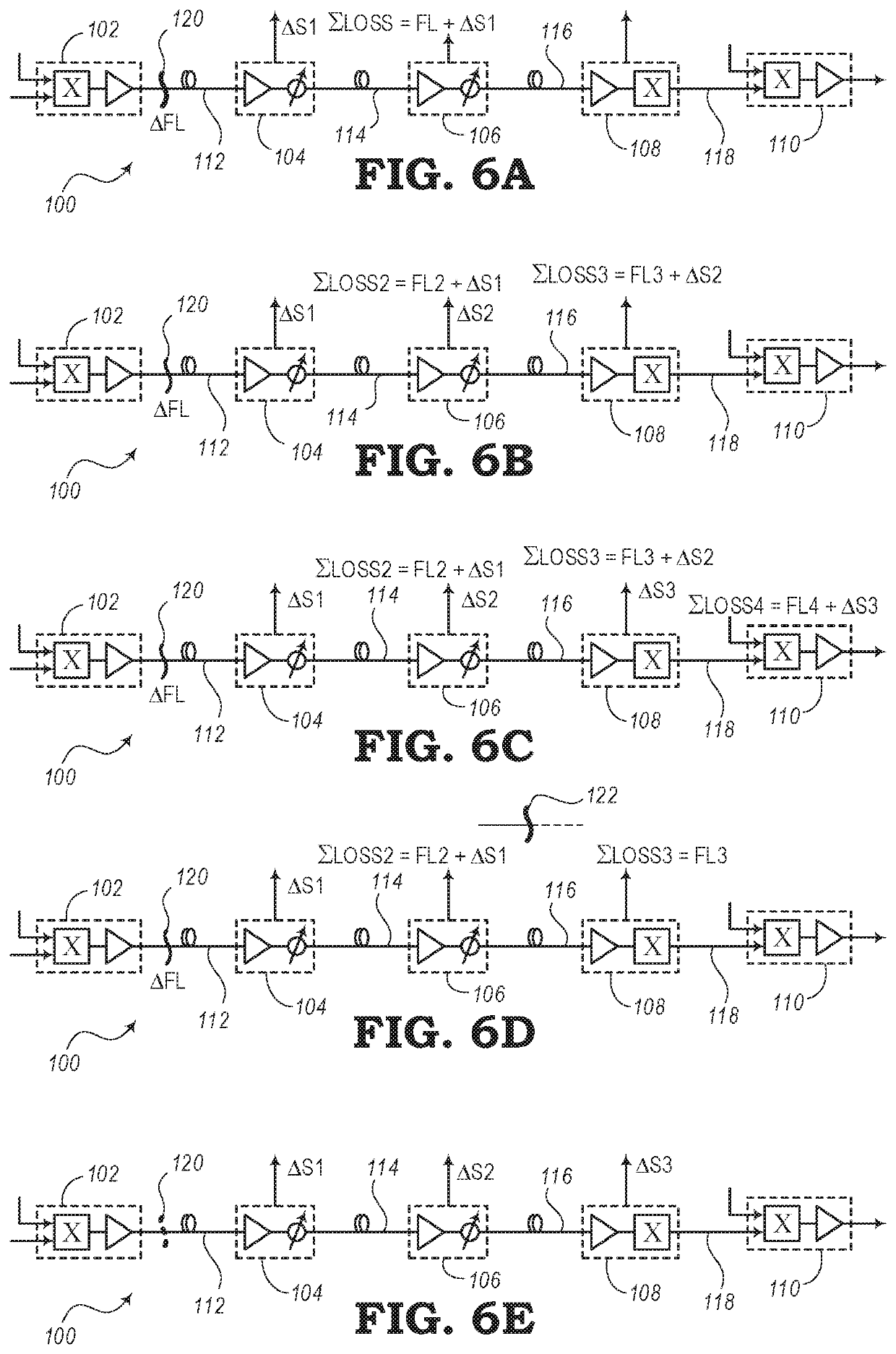
[0020]The present disclosure relates to systems and methods for compensating for power loss over fiber links of optical networks and photonic line systems. In addition to transmission loss that may be expected to occur over a given length of optical fiber, a fiber link may experience additional power losses. For example, a pinch in a fiber link may cause above-average losses. A fiber pinch may be the result of a fiber that is folded or bent beyond an acceptable bend radius or a fiber that has been compressed. Compression, for instance, may come from devices (e.g., zip ties, etc.) for keeping a group of cables together, a tool (e.g., pliers, etc.), wrapping fibers around a sharp corner, or from other situations where a fiber optic cable may experience less than optimal treatment.

[0021]Controllers may be arranged through a photonic line system to measure the total losses at a receiving end of a fiber link. The total losses (or accumulated losses) represent a loss in transmission power...


PUM


Abstract

Systems and methods for measuring accumulated power losses over a fiber link are described in the present disclosure. According to one embodiment, a method includes the step of measuring accumulated losses over a fiber link. The method also includes the step of at least partially compensating for the measured accumulated losses. In response to determining that there is a compensation shortfall with respect to the accumulated losses, the method includes the step of transmitting the compensation shortfall to one or more downstream controllers.

Description

TECHNICAL FIELD[0001]The present disclosure generally relates to optical network systems and methods. More particularly, the present disclosure relates to measuring losses in a fiber link of a photonic line system and distributing compensation to downstream controllers.BACKGROUND[0002]Generally, in the field of optical networking systems, data is communicated throughout an optical system along a number of optical fiber cables, fiber links, fiber spans, etc. Typically, signals lose power or attenuate at a predictable rate as they traverse a length of fiber. Thus, optical amplifiers may be arranged throughout the system to amplify the gain of the signals to a level where the signals can be received with sufficient power at the next node or element in the system.[0003]Some amplifiers may be designed with associated controllers that can measure the amount of attenuation and correspondingly increase the gain of the amplifiers to compensate for the power loss. However, controllers are typ...

Claims


Application Information

Patent Timeline
Patent Type & Authority Patents(United States)
IPC IPC(8): H04B10/08H04B10/079H04B10/564
CPCH04B10/07955H04B10/0791H04B10/0799H04B10/564H04B10/0797
Inventor AL SAYEED, CHOUDHURY A.MIEDEMA, DAVID J.ATKINSON, DAVID
Owner CIENA
Why Eureka
Try Eureka