Supercharge Your Innovation With Domain-Expert AI Agents!

Liquid crystal display device

a liquid crystal display and display device technology, applied in non-linear optics, instruments, optics, etc., can solve the problem that the horizontal alignment mode liquid crystal display device cannot switch between on and off, and achieve the effect of suppressing light leakage and reducing the reflection of external ligh

Active Publication Date: 2021-04-27
SHARP KK
View PDF6 Cites 0 Cited by
  • Summary
  • Abstract
  • Description
  • Claims
  • Application Information

AI Technical Summary

Benefits of technology

The present invention provides a liquid crystal display device that can reduce reflection of external light and suppress light leakage when viewed from oblique directions in the black display state. This is achieved by using an out-cell retardation layer and an in-cell retardation layer that work together to cancel out the retardation of the in-cell retardation layer at all azimuths. This invention improves the display quality of liquid crystal display devices and provides a better viewing experience for users.

Problems solved by technology

The horizontal alignment mode liquid crystal display device unfortunately fails to switch between on and off when circularly polarized light is incident on the liquid crystal layer.

Method used


Image

  • Liquid crystal display device
  • Liquid crystal display device
  • Liquid crystal display device

Examples


embodiment 1

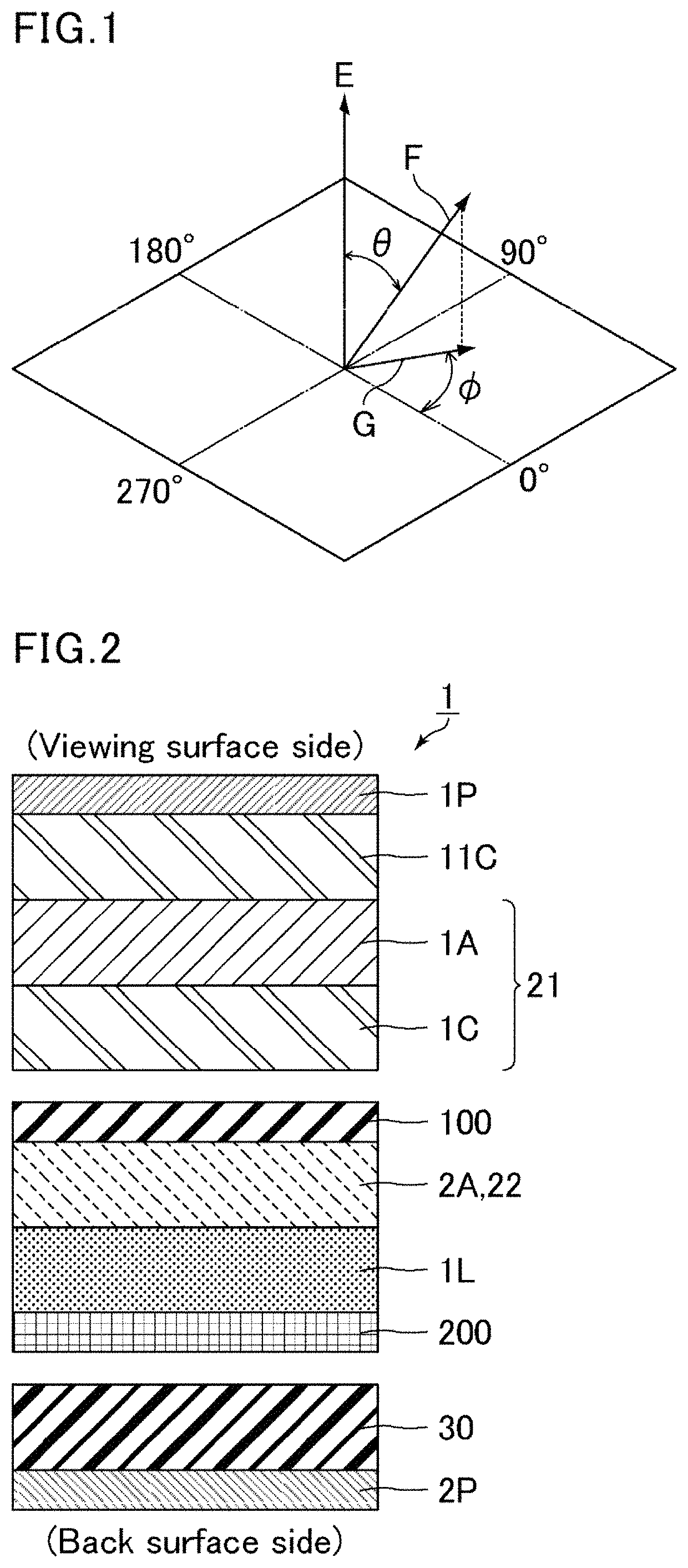
[0094]FIG. 2 is a schematic cross-sectional view of a liquid crystal display device of Embodiment 1. A liquid crystal display device 1 of the present embodiment includes, in the following order from the viewing surface side, a first polarizer 1P, a first positive A plate 1A having an in-plane retardation of 120 nm or greater and 155 nm or smaller, a positive C plate 1C having a thickness retardation of 80 nm or greater and 100 nm or smaller, a first substrate 100, a second positive A plate 2A having an in-plane retardation of 120 nm or greater and 155 nm or smaller, a horizontally aligned liquid crystal layer 1L, a second substrate 200, a viewing angle compensation layer 30, and a second polarizer 2P. The liquid crystal display device 1 further includes between the first polarizer 1P and the first positive A plate 1A a positive C plate 11C having a thickness retardation of 30 nm or greater and 80 nm or smaller.

[0095]The first substrate 100 includes, in the following order from the v...

embodiment 1-1

(Embodiment 1-1)

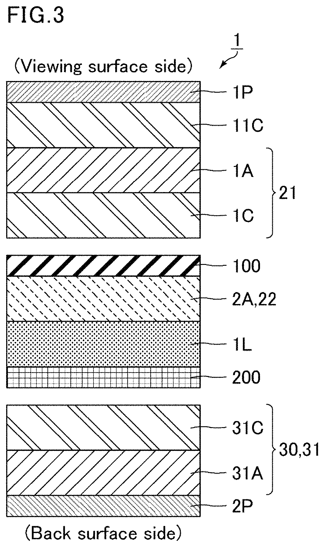
[0126]FIG. 3 is a schematic cross-sectional view of a liquid crystal display device of Embodiment 1-1. As shown in FIG. 3, the viewing angle compensation layer 30 in a liquid crystal display device 1 of the present embodiment is a first laminate 31 including, in the following order from the second polarizer 2P side, a positive A plate 31A having an in-plane retardation of 130 nm or greater and 150 nm or smaller and a positive C plate 31C having a thickness retardation of 80 nm or greater and 100 nm or smaller.

[0127]The positive A plate 31A has an in-plane retardation of preferably 132 nm or greater and 148 nm or smaller, more preferably 135 nm or greater and 145 nm or smaller.

[0128]The positive A plate 31A has an NZ coefficient of preferably 0.8 or greater and 1.2 or smaller, more preferably 0.9 or greater and 1.1 or smaller.

[0129]The positive A plate 31A may be formed by the same method as for the positive A plate 1A.

[0130]The positive C plate 31C has a thickness re...

embodiment 1-2

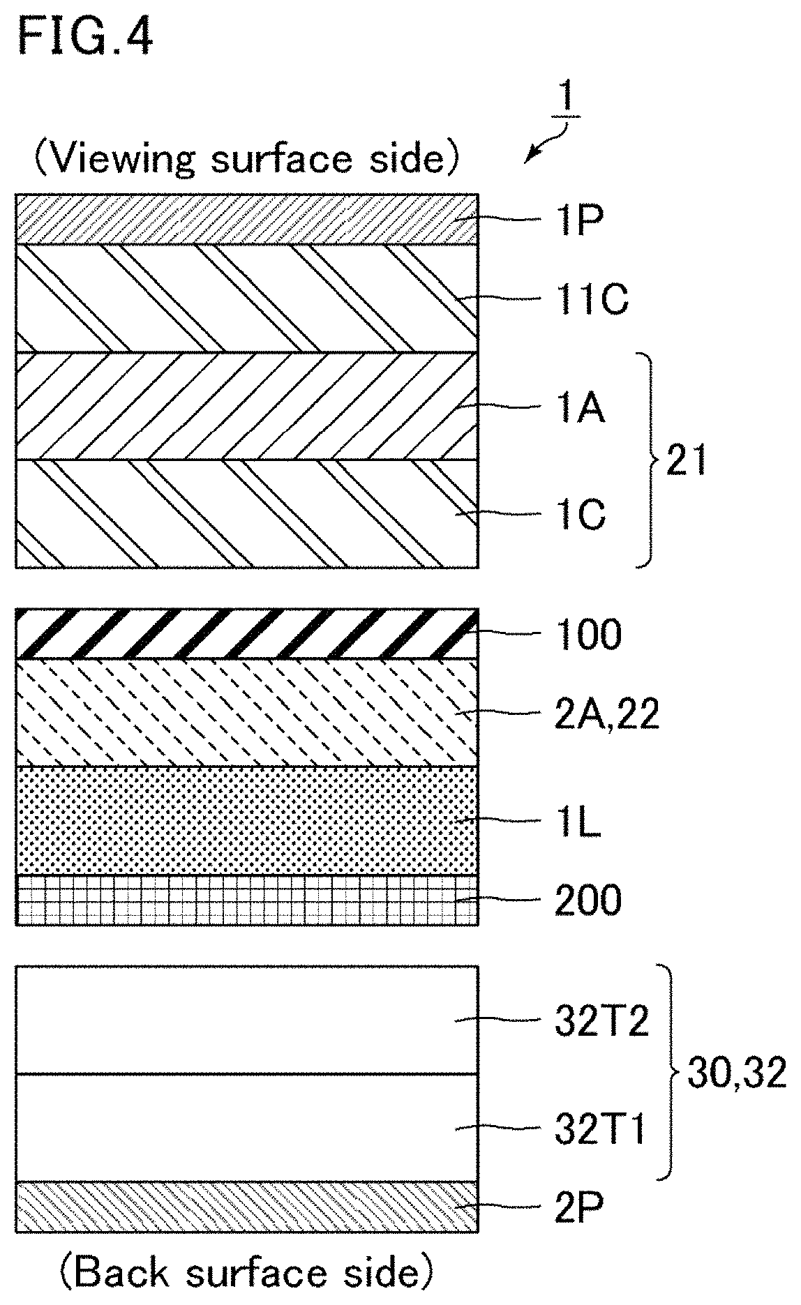
[0133]FIG. 4 is a schematic cross-sectional view of a liquid crystal display device of Embodiment 1-2. As shown in FIG. 4, the viewing angle compensation layer 30 in a liquid crystal display device 1 of the present embodiment is a second laminate 32 including, in the following order from the second polarizer 2P side, a biaxial retardation layer 32T1 having an in-plane retardation of 80 nm or greater and 100 nm or smaller and an NZ coefficient of 1.3 or greater and 1.5 or smaller and a biaxial retardation layer 32T2 having an in-plane retardation of 50 nm or greater and 70 nm or smaller and an NZ coefficient of −1.2 or greater and −0.8 or smaller.

[0134]The biaxial retardation layer 32T1 may be formed by simultaneous biaxial stretching or sequential biaxial stretching on a material with a positive birefringence, for example. Specific examples of the material with a positive birefringence include the same as the examples for the materials of the resin film for a positive A plate.

[0135]...


PUM

PropertyMeasurementUnit
thickness retardationaaaaaaaaaa

Abstract

A liquid crystal display device of the present invention includes in the following order from a viewing surface side a first polarizer, a first positive A plate having an in-plane retardation of 120 nm or greater and 155 nm or smaller, a positive C plate having a thickness retardation of 80 nm or greater and 100 nm or smaller, a first substrate, a second positive A plate having an in-plane retardation of 120 nm or greater and 155 nm or smaller, a horizontally aligned liquid crystal layer, a second substrate, a viewing angle compensation layer, and a second polarizer. The device further includes between the first polarizer and the first positive A plate a positive C plate having a thickness retardation of 30 nm or greater and 80 nm or smaller.

Description

CROSS-REFERENCE TO RELATED APPLICATIONS[0001]The present application claims priority under 35 U.S.C. § 119 to U.S. Provisional Application No. 62 / 739,114 filed on Sep. 28 2018, the contents of which are incorporated herein by reference in their entirety.BACKGROUND OF THE INVENTIONField of the Invention[0002]The present invention relates to liquid crystal display devices. The present invention specifically relates to a liquid crystal display device including a horizontally aligned liquid crystal layer.Description of Related Art[0003]Liquid crystal display devices use a liquid crystal composition for display. According to a typical display mode, voltage is applied to a liquid crystal composition sealed between a pair of substrates to change the alignment of liquid crystal molecules in the liquid crystal composition according to the applied voltage, whereby the amount of light transmitted is controlled. Such liquid crystal display devices have advantageous features such as thin profile...

Claims


Application Information

Patent Timeline
Patent Type & Authority Patents(United States)
IPC IPC(8): G02F1/1335G02F1/13363
CPCG02F1/133528G02F1/13363G02F1/133634G02F2001/133531G02F2413/04G02F1/133531
Inventor HASEGAWA, MASAHIROSAKAI, AKIRAKOIDE, TAKAKOKAWAHIRA, YUICHIMURATA, KOJIMINOURA, KIYOSHI
Owner SHARP KK
Features
  • R&D
  • Intellectual Property
  • Life Sciences
  • Materials
  • Tech Scout
  • Unparalleled Data Quality
  • Higher Quality Content
  • 60% Fewer Hallucinations
Learn More