
Power saw blade cooling arrangement

a cooling arrangement and power saw technology, applied in the field of cutting machines, can solve the problems of inability to collect residual particles, motor burns or permanent damage, and the majority of liquid coolant cannot be left on or around the cutting saw, so as to reduce the amount of cooling fluid, minimize the formation of dust, and minimize the moisture build up within the blade casing

Active Publication Date: 2021-05-04
LEE CHAO YING
View PDF29 Cites 0 Cited by
  • Summary
  • Abstract
  • Description
  • Claims
  • Application Information

AI Technical Summary

Benefits of technology

[0009]Another advantage of the invention is to a cutting machine, wherein no excessive cooling fluid is stayed on the cutting blade to minimize the formation of dust, and misting of the cooling fluid during the cutting operation.
[0010]Another advantage of the invention is to a cutting machine, wherein the cooling fluid is stayed on the cutting blade by means of adhesion and cohesion of the cooling fluid to minimize moisture built up within the blade casing and to reduce the amount of cooling fluid being used for cooling the cutting blade.
[0011]Another advantage of the invention is to a cutting machine, wherein the cooling fluid further acts as a lubricant which does cool the cutting blade by allowing the cutting blade to encounter less friction as it cuts away the work piece.
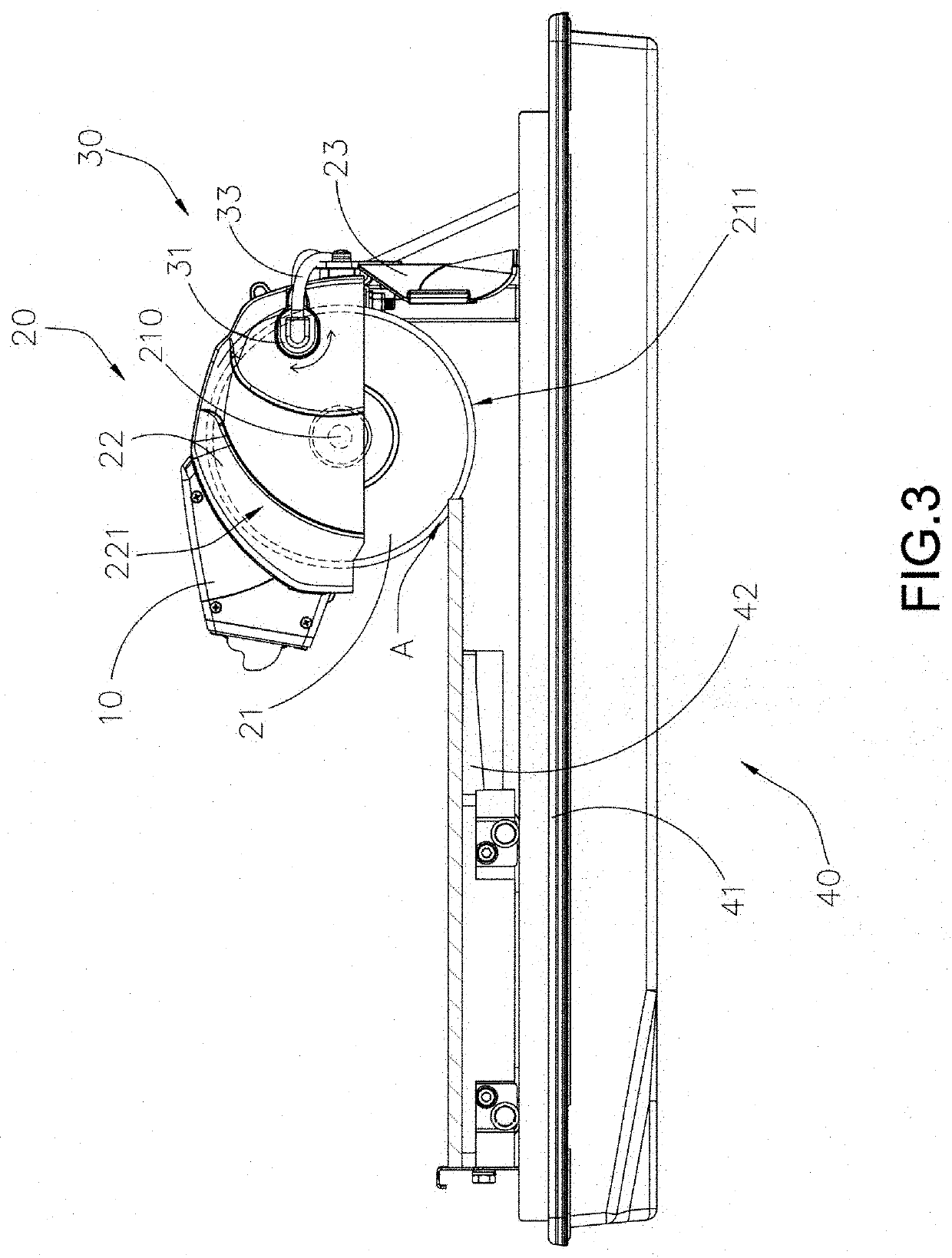
[0012]Another advantage of the invention is to a cutting machine, wherein the injecting angle of the fluid nozzle unit is set at a rearward direction with respect to the cutting machine for preventing the cooling fluid stayed on the cutting blade in an over-saturated manner. In particular, the injecting angle is aligned with a radial direction of the cutting blade.
[0013]Another advantage of the invention is to a cutting machine, wherein the cooling fluid with the residual particles of the work piece is deflected to be diverted by the splash guard to control the liquid's area of affect so as to prevent puddles of cooling fluid created on the job site.
[0014]Another advantage of the invention is to a cutting machine, wherein the power saw blade cooling arrangement can be incorporated with any existing cutting machine having the rotatable cutting blade.

Problems solved by technology

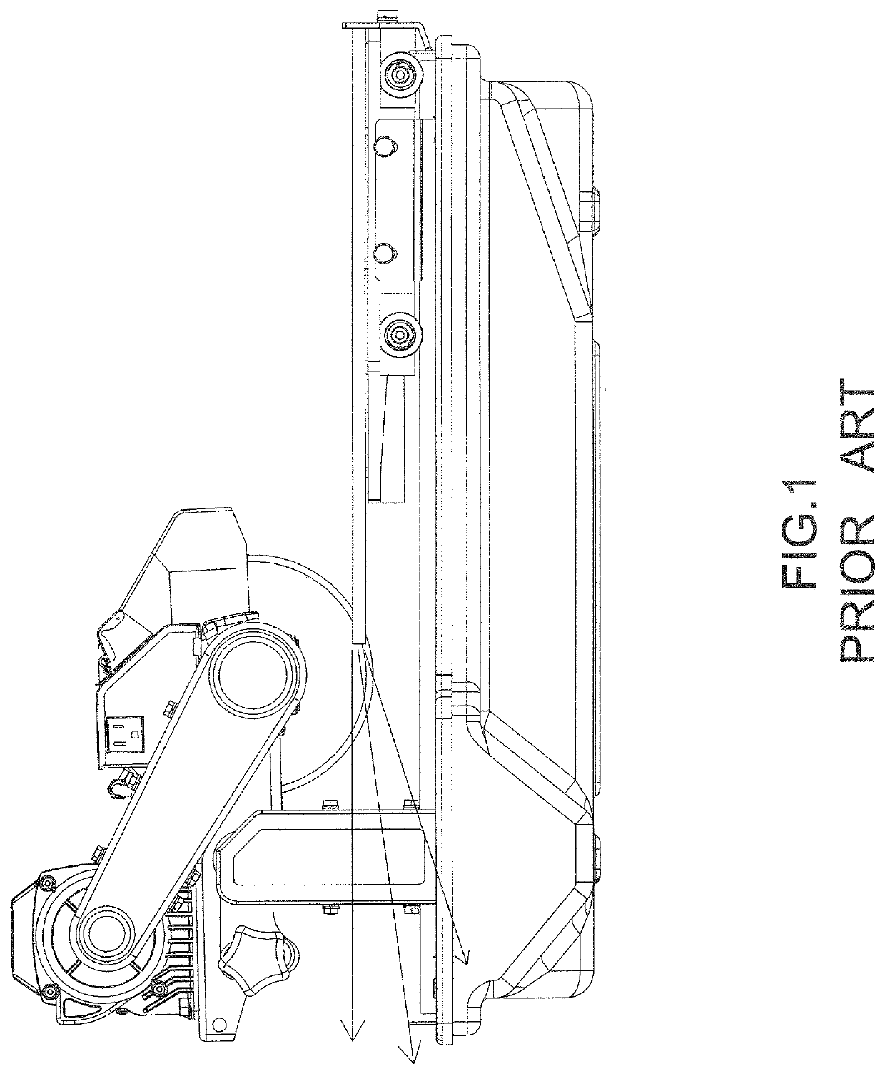
Therefore, the prior art methodology for saw cooling is to deliver as much liquid coolant on the cutting saw and the work piece, which creates puddles of liquid coolant on the job site.
It is a waste that most of the liquid coolant cannot be remains on or around the cutting saw because of the centrifugal force of the cutting saw during the cutting operation.
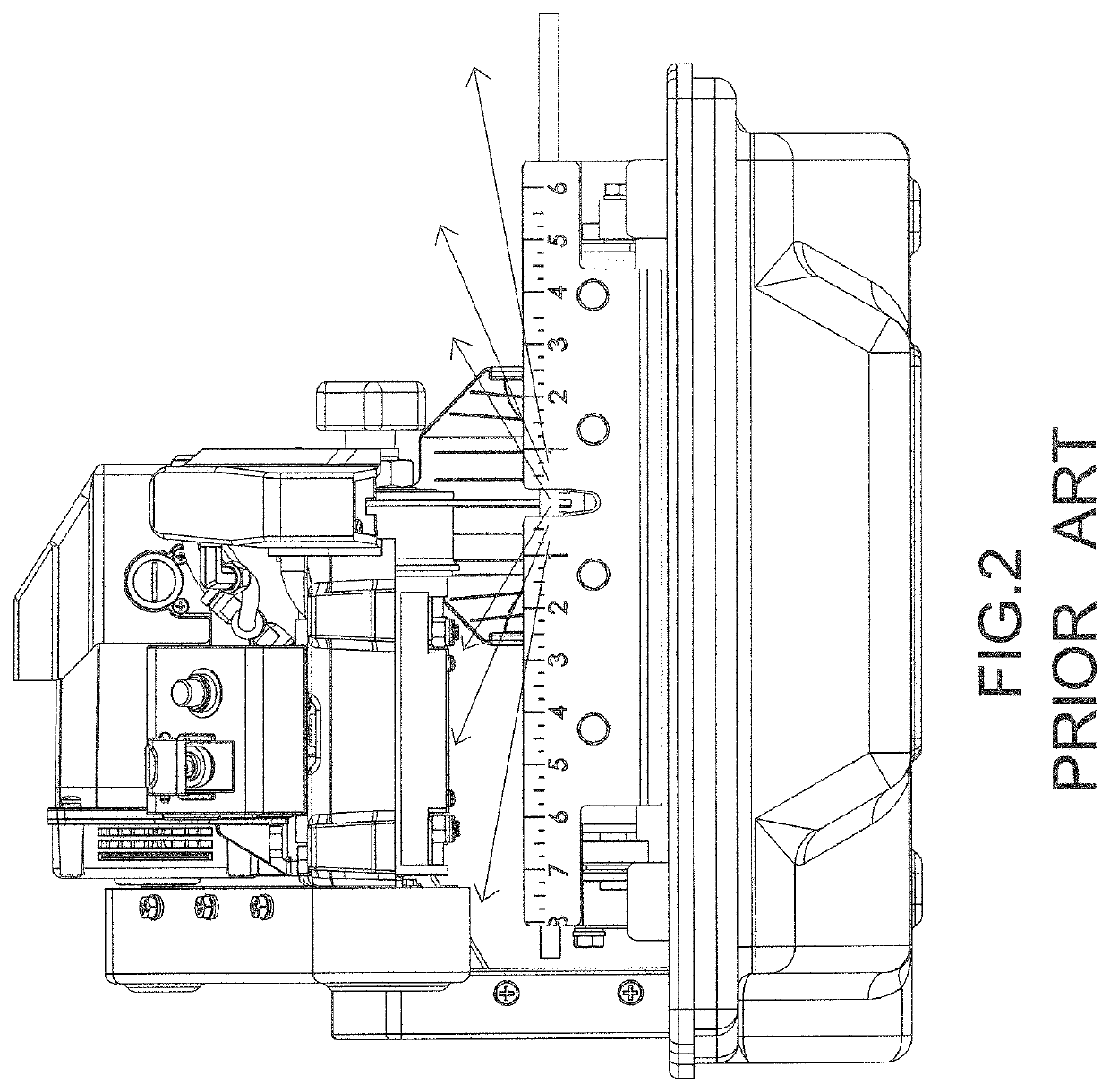
However, it is impossible to collect residual particles and the liquid coolant splashed from the cutting blade at the sideward direction.
Therefore, the motor may be burned or permanent damage while the residual particles gradually accumulate to the motor.

Method used


Image

  • Power saw blade cooling arrangement
  • Power saw blade cooling arrangement
  • Power saw blade cooling arrangement

Examples


Embodiment Construction

[0028]The following description is disclosed to enable any person skilled in the art to make and use the present invention. Preferred embodiments are provided in the following description only as examples and modifications will be apparent to those skilled in the art. The general principles defined in the following description would be applied to other embodiments, alternatives, modifications, equivalents, and applications without departing from the spirit and scope of the present invention.

[0029]Referring to FIGS. 3 and 4 of the drawings, a cutting machine for cutting a work piece according to a preferred embodiment of the present invention is illustrated, wherein the cutting machine comprises a motor assembly 10, a cutting head arrangement 20, and a power saw blade cooling arrangement 30.

[0030]Accordingly, the cutting machine can be a hand-held machine, wherein a carrying handle is provided, such that a user is able to carry the cutting machine via the carrying handle to cut the w...


PUM

PropertyMeasurementUnit
frictionaaaaaaaaaa
injecting angleaaaaaaaaaa
flexibleaaaaaaaaaa

Abstract

A cutting machine includes a motor assembly, a cutting blade powered by the motor assembly for cutting a work piece, and a cooling arrangement which includes a fluid nozzle unit for delivering cooling fluid onto a cutting edge portion of the cutting blade to ensure the cooling fluid to adhere on the cutting blade by means of adhesion and cohesion of the cooling fluid so as to cool the cutting blade during the cutting operation and to combine the cooling fluid with residual particles of the work piece after the work piece is cut. Therefore, no excessive cooling fluid is stayed on the cutting blade to minimize the formation of dust, and misting of the cooling fluid during the cutting operation.

Description

NOTICE OF COPYRIGHT[0001]A portion of the disclosure of this patent document contains material which is subject to copyright protection. The copyright owner has no objection to any reproduction by anyone of the patent disclosure, as it appears in the United States Patent and Trademark Office patent files or records, but otherwise reserves all copyright rights whatsoever.BACKGROUND OF THE PRESENT INVENTION[0002]Field of Invention[0003]The present invention relates to a cutting machine, and more particularly to a cutting machine with a power saw blade cooling arrangement, which is arranged for directly cooling the cutting blade of the cutting machine and for effectively collecting the residual particles during the cutting process so as to reduce the pollution of spitting out of the residual particles. The cooling fluid further acts as a lubricant which does cool the cutting blade by allowing the cutting blade to encounter less friction as it cuts away the work piece.[0004]Description ...

Claims


Application Information

Patent Timeline
Patent Type & Authority Patents(United States)
IPC IPC(8): B28D7/02B23D59/02B28D1/04
CPCB28D7/02B23D59/02B28D1/04
Inventor LEE, CHAO-YING
Owner LEE CHAO YING
Learn More