Radio frequency-based repeater in a waveguide system

a frequency-based repeater and waveguide technology, applied in the field of electromagnetic communication, can solve the problems of increasing the number of system components, increasing failure probabilities, and the inability of troubleshooting systems to identify the contributing faulty components reliably

Active Publication Date: 2021-05-04
RTX CORP
View PDF81 Cites 8 Cited by
  • Summary
  • Abstract
  • Description
  • Claims
  • Application Information

AI Technical Summary

Problems solved by technology

As control and health monitoring systems become more complex, the interconnect count between system components increases, which also increases failure probabilities.
With the increase in interconnects, troubleshooting systems may not always identify the contributing faulty components reliably when system anomalies occur.
Failures associated with such systems are often due to connection system failures, including: sensors, wiring, and connectors that provide interconnection (e.g., signal and power) between all components.
Difficulties can arise when troubleshooting these complex interconnected systems, especially when the systems include subsystems having electronic components connected to control system devices, such as actuators, valves or sensors.
For example, a noisy signal in a sensor reading could be caused by a faulty interface circuit in the electronic component, a faulty wire or short(s) in the cable system, and / or a faulty or intermittent sensor.
The time associated with identifying a faulty component quickly and accurately affects operational reliability.
The access limitations make wire routing bulky, expensive and vulnerable to interconnect failures.
The sensor and interconnect operating environments for desired sensor locations often exceed the capability of the interconnect systems.
In some cases, cable cost, volume and weight exceed the desired limits for practical applications.
Application of electromagnetic sensor and effector technologies to address the wiring constraints faces the challenge of providing reliable communications in a potentially unknown environment with potential interference from internal or external sources.
Large-scale deployments of multiple sensors and / or effectors with varying signal path lengths further increases the challenges of normal operation and fault detection in a network of connected nodes.

Method used


Image

  • Radio frequency-based repeater in a waveguide system
  • Radio frequency-based repeater in a waveguide system
  • Radio frequency-based repeater in a waveguide system

Examples


Embodiment Construction

[0026]A detailed description of one or more embodiments of the disclosed apparatus and method are presented herein by way of exemplification and not limitation with reference to the Figures.

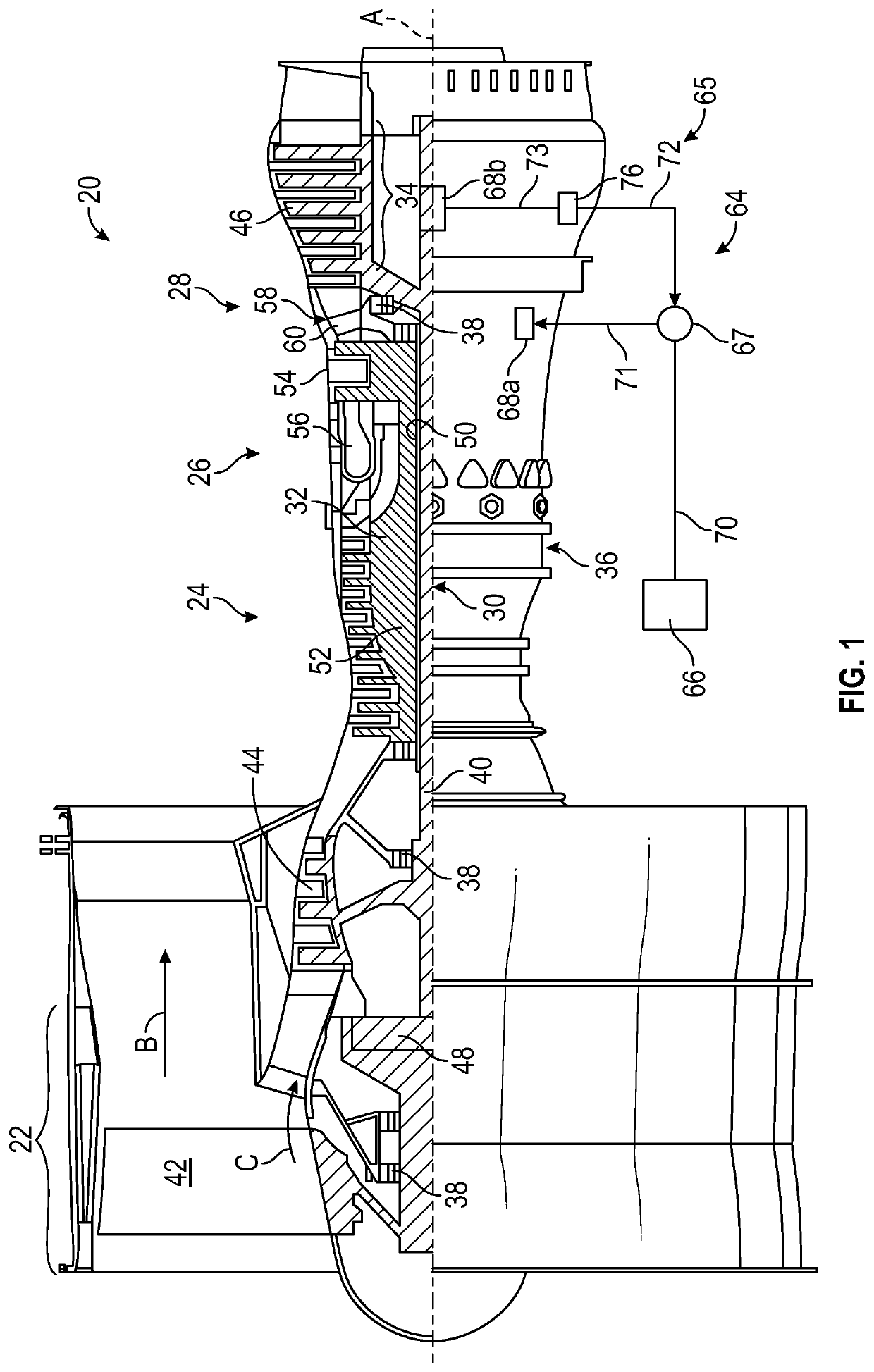
[0027]Various embodiments of the present disclosure are related to electromagnetic communication through and to components of a machine. FIG. 1 schematically illustrates a gas turbine engine 20 as one example of a machine as further described herein. The gas turbine engine 20 is depicted as a two-spool turbofan that generally incorporates a fan section 22, a compressor section 24, a combustor section 26 and a turbine section 28. Alternative engines may include an augmentor section (not shown) among other systems or features. The fan section 22 drives air along a bypass flow path B in a bypass duct to provide a majority of the thrust, while the compressor section 24 drives air along a core flow path C for compression and communication into the combustor section 26 then expansion through the turbin...


PUM


Abstract

A system of a machine includes a network of a plurality of nodes distributed throughout the machine. Each of the nodes is operable to communicate through a plurality of electromagnetic signals. A controller is operable to communicate with the network of nodes through the electromagnetic signals. The system also includes a plurality of waveguides configured to guide transmission of the electromagnetic signals between the controller and one or more of the nodes. A radio frequency-based repeater is coupled to at least two of the waveguides in the network between the controller and at least one of the nodes. The radio frequency-based repeater is configured to receive a portion of the electromagnetic signals in a first waveguide and boost a transmission characteristic of the portion of the electromagnetic signals in a second waveguide.

Description

BACKGROUND[0001]This disclosure relates to electromagnetic communication, and more particularly to a radio frequency-based repeater in a waveguide system.[0002]As control and health monitoring systems become more complex, the interconnect count between system components increases, which also increases failure probabilities. With the increase in interconnects, troubleshooting systems may not always identify the contributing faulty components reliably when system anomalies occur. Failures associated with such systems are often due to connection system failures, including: sensors, wiring, and connectors that provide interconnection (e.g., signal and power) between all components.[0003]Difficulties can arise when troubleshooting these complex interconnected systems, especially when the systems include subsystems having electronic components connected to control system devices, such as actuators, valves or sensors. For example, a noisy signal in a sensor reading could be caused by a fau...

Claims


Application Information

Patent Timeline
Patent Type & Authority Patents(United States)
IPC IPC(8): H04B7/155F02C9/00
CPCH04B7/15528F02C9/00H04B3/36H04B3/52
Inventor GILSON, JONATHANMANTESE, JOSEPH V.DJUKNIC, GORANGOK, GURKANLISITANO, BRENDA J.BAJEKAL, SANJAYWOOD, COY BRUCE
Owner RTX CORP
Why Eureka
Try Eureka