Clutch and motor

a technology of clutch housing and roller, which is applied in the direction of wing accessories, mechanical equipment, gearing, etc., can solve the problems of insufficient grease between the inner circumferential surface of the clutch housing and the roller, and it is difficult to sandwich the roller with the inner circumferential surface, so as to prevent greas

Active Publication Date: 2021-05-11
DENSO CORP
View PDF12 Cites 0 Cited by
  • Summary
  • Abstract
  • Description
  • Claims
  • Application Information

AI Technical Summary

Benefits of technology

Problems that are to be Solved by the Invention
[0006]It is an object of the present invention to provide a clutch and a motor capable of preventing grease between the inner circumferential surface of a clutch housing and rollers from becoming insufficient.

Problems solved by technology

This results in the amount of grease between the inner circumferential surface of the clutch housing and the rollers being insufficient.
If there is not enough grease between the inner circumferential surface of the clutch housing and the rollers, it may become difficult to sandwich the rollers with the inner circumferential surface of the clutch housing and the driven side rotating body when the rotation shaft is not rotationally driven (difficult to serve as wedges).

Method used


Image

  • Clutch and motor
  • Clutch and motor
  • Clutch and motor

Examples


first embodiment

[0046]A first embodiment of a motor including a clutch will now be described.

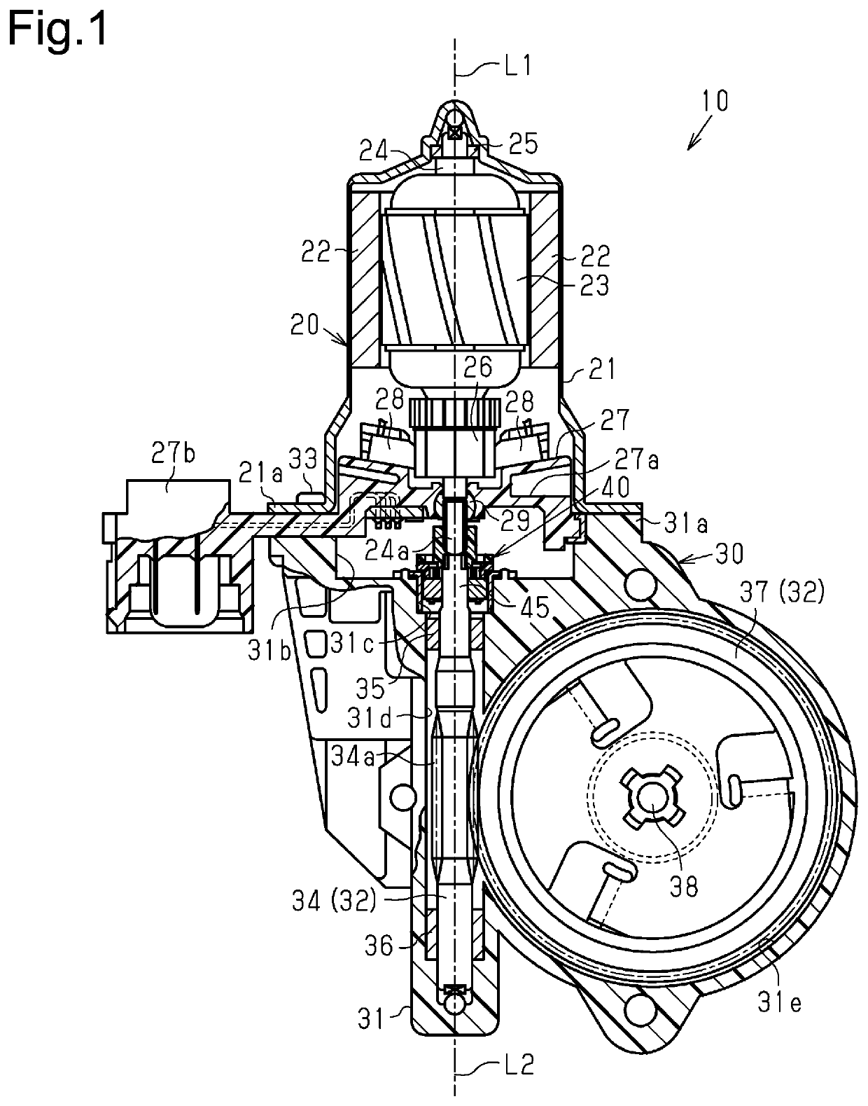
[0047]A motor 10 of the first embodiment shown in FIG. 1 is provided in a power window device for electrically raising and lowering a vehicle window glass. The motor 10 includes a motor unit 20 for producing torque and an output unit 30 for decelerating and outputting rotation outputted by the motor unit 20, which are assembled into one body. Further, the motor 10 includes a clutch 40 at a drive connecting portion between the motor unit 20 and the output unit 30.

[0048]The motor unit 20 of the first embodiment is formed by a DC motor. Magnets 22 are fixed to the inner circumferential surface of a bottomed tubular yoke housing (hereinafter referred to as the yoke 21) forming the motor unit 20, and an armature 23 is arranged inside the magnets 22. The armature 23 has a rotation shaft 24 arranged in a central portion of the yoke 21. A proximal end portion (upper end portion in FIG. 1) of the rotation shaft 24 i...

second embodiment

[0133]A second embodiment of a motor including a clutch will now be described. Same reference numerals are given to those components that are the same as the corresponding components of the first embodiment. Such components will not be described in detail.

[0134]As shown in FIGS. 19 and 20, the support member 43 holds rollers 144 between the clutch housing 41 and the driven side rotating body 45 radially facing each other. The support member 43 of the second embodiment is made of resin.

[0135]As shown in FIGS. 20, 21A, and 21B, each roller holding portion 62 has an axial opposed portion (axial support portion) 63 that extends radially inward from the ring 61 and faces the roller 144 in the central axis L1 direction (that is, rotation axis direction of drive side rotating body 42). Each roller holding portion 62 also has two roller supports 164a and 164b (rotational direction opposed portions) extended to the opposite side of the ring 61 (downward in FIG. 21A) along the central axis L1...

third embodiment

[0168]A third embodiment of a clutch will now be described. Same reference numerals are given to those components that are the same as the corresponding components of the second embodiment. Such components will not be described in detail.

[0169]A support member 200 and rollers 210 of the third embodiment shown in FIGS. 27A and 27B are provided in the clutch 40 of the second embodiment in place of the support member 43 and the rollers 144 (refer to FIG. 20).

[0170]An engaging protrusion (support member side engaging portion) 201 protruding in the rotation axis (same as central axis L1) direction of the drive side rotating body 42 is formed at the axial opposed portion 63 of each roller holding portion 62 of the support member 200. Each engaging protrusion 201 of the third embodiment protrudes in the central axis L1 direction from a radially outer end portion of the axial opposed portion 63 toward the distal end side of the roller supports 164a and 164b. In each roller holding portion 6...


PUM


Abstract

A clutch includes a roller arranged between a clutch housing and a driven side rotating body. The roller is rotated about a rotation axis of a drive side rotating body together with the drive side rotating body when the drive side rotating body is rotationally driven. The roller hinders rotation of the driven side rotating body by being sandwiched between the clutch housing and the driven side rotating body when the drive side rotating body is not rotationally driven. The support member sandwiches the roller between the clutch housing and the driven side rotating body. The support member rotates about the rotation axis of the drive side rotating body together with the drive side rotating body. The grease is arranged between the clutch housing and the roller. The support member restricts rotation of the roller about a central axis of the roller.

Description

TECHNICAL FIELD[0001]The present invention relates to a clutch and a motor including the clutch.BACKGROUND ART[0002]A conventional motor used as a drive source of a power window device or the like installed in a vehicle includes a motor unit having a rotation shaft that is rotationally driven and an output unit having a driven shaft to which the rotational driving force of the rotation shaft is transmitted to output the rotational driving force transmitted to the driven shaft. Patent document 1 describes an example of the rotation shaft and the driven shaft that are connected by a clutch functioning to transmit the rotational driving force of the rotation shaft to the driven shaft and not transmit rotational force from the driven shaft side to the rotation shaft.[0003]The clutch described in patent document 1 includes a drive side rotating body rotated integrally with the rotation shaft, a driven side rotating body rotated integrally with the driven shaft and configured to be engage...

Claims


Application Information

Patent Timeline
Patent Type & Authority Patents(United States)
IPC IPC(8): F16D41/069F16D41/10
CPCF16D41/069F16D41/105E05Y2201/216E05Y2201/234F16H1/16E05F15/697F16D3/02F16D51/50F16D51/22F16D67/02
Inventor OGURI, RYOUSUKESHIRAI, NAKATSUNEOZAKI, TOMOAKIKIJIMA, SHUSUKESUZUKI, KENTASAWAMOTO, DAISUKEOHARA, AKIYOSHIOKADA, HIROYUKI
Owner DENSO CORP
Why Eureka
Try Eureka