Special reinforced bearing for self-lubricating high-temperature guide rail
A self-lubricating and bearing technology, applied in the direction of ball bearings, shafts and bearings, bearing components, etc., can solve the problems of increasing the smoothness of bearing operation and the ability to resist adhesion of impurities, so as to increase the ability of resistance to adhesion of impurities and ensure flexible operation performance, increase the effect of smooth running
- Summary
- Abstract
- Description
- Claims
- Application Information
AI Technical Summary
Problems solved by technology
Method used
Image
Examples
Embodiment 1
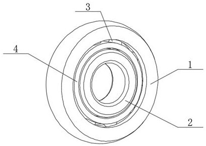
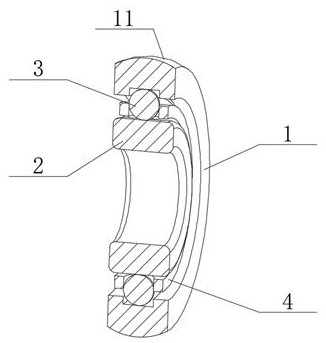
[0036] like Figure 1-2 As shown, the present invention provides a technical solution: a special reinforced bearing for self-lubricating high-temperature guide rails, including a bearing outer ring 1 and a reinforced inner ring 2, the reinforced inner ring 2 is located inside the bearing outer ring 1, and the reinforced inner ring 2 and the bearing Rollers 3 are arranged between the outer rings 1, and composite protectors 4 are arranged on the periphery of the rollers 3. The highest point of the synapse 11 is located on the center line of the bearing outer ring 1, and an arc-shaped groove is opened inside the bearing outer ring 1, and the upper half of the roller 3 is located inside the arc-shaped groove.
[0037] In this embodiment, the cylindrical surface of the outer diameter of the traditional bearing is changed to an arc-shaped synapse 11 in the state of a large arc surface, so that the contact between the outer ring of the bearing 1 and the guide rail changes from a line...
Embodiment 2
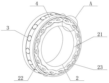
[0039] like image 3 and Figure 5 As shown, the reinforced inner ring 2 includes a closed outer layer 21 and a reinforced inner layer 22, the closed outer layer 21 is covered on the outer wall of the reinforced inner layer 22, and a dispersion panel 23 is arranged between the closed outer layer 21 and the reinforced inner layer 22. The inner wall of the protector 4 is overlapped on the outer wall of the reinforced inner layer 22, the dispersion panel 23 includes an independent support net 231, a receiving groove 232 and an expansion through hole 233, and the bottom of the independent support net 231 is installed on the outer wall of the reinforced inner layer 22 , the expansion through hole 233 is located at the center of the independent support network 231 , and the expansion through hole 233 is located at the edge of the independent support network 231 .
[0040]In this embodiment, the closed outer layer 21 and the reinforced inner layer 22 together form the reinforced inn...
Embodiment 3
[0042] like Figure 4 and 6 As shown, the composite protector 4 includes a restricting outer ring 41, a docking inner ring 42 and a positioning splint 43, the number of the restricting outer ring 41, the docking inner ring 42 and the positioning splint 43 are two, and one side of the docking inner ring 42 is connected On one side of limiting the outer ring 41, the positioning splint 43 is installed on the other side of the docking inner ring 42, and the other side of the positioning splint 43 is connected with another positioning splint 43, and the roller 3 is positioned at the inside of the positioning splint 43. Clamping plate 43 comprises fixed inner core 431, partition shell 432 and positioning ring 433, and one end of fixed inner core 431 is connected on the inner wall of positioning ring 433, and one end of partition shell 432 is connected at the edge of positioning ring 433, and the fixed inner The core 431 is located inside the partition shell 432, and the intersectio...
PUM
 Abstract
Description
Claims
Application Information
 - R&D
- Intellectual Property
- Life Sciences
- Materials
- Tech Scout
- Unparalleled Data Quality
- Higher Quality Content
- 60% Fewer Hallucinations
Browse by: Latest US Patents, China's latest patents, Technical Efficacy Thesaurus, Application Domain, Technology Topic, Popular Technical Reports.
© 2025 PatSnap. All rights reserved.Legal|Privacy policy|Modern Slavery Act Transparency Statement|Sitemap|About US| Contact US: help@patsnap.com


