Saw blade separation device for band sawing machine

A partition device and band saw machine technology, applied in band saws, sawing equipment, wood processing equipment, etc., can solve the problems of high processing cost, poor board quality, long processing time, etc., achieve long service life and wide application range , The effect of saving processing costs

Inactive Publication Date: 2016-04-13
张家铭 +2
View PDF6 Cites 1 Cited by
  • Summary
  • Abstract
  • Description
  • Claims
  • Application Information

AI Technical Summary

Problems solved by technology

[0014] The object of the present invention is to provide an improved saw blade partitioning device for band saw machines, which can overcome the restrictions on easily deformed materials in the prior art when sawing boards, because the saw blades are easily clipped by the boards after sawing, resulting in The quality of the processed plate is poor, the utilization rate is low, the processing time is long, the loss of the saw blade is large, and the processing cost is high.

Method used


Image

  • Saw blade separation device for band sawing machine
  • Saw blade separation device for band sawing machine
  • Saw blade separation device for band sawing machine

Examples


Embodiment 1

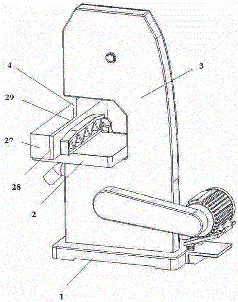
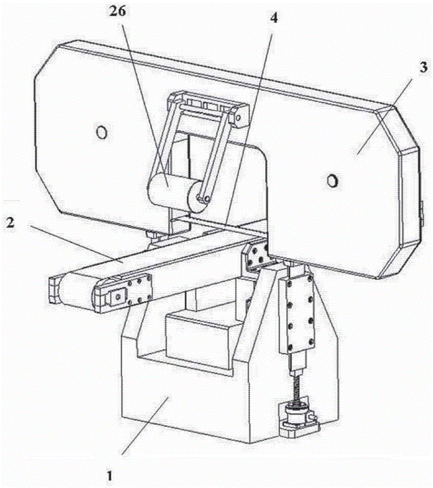
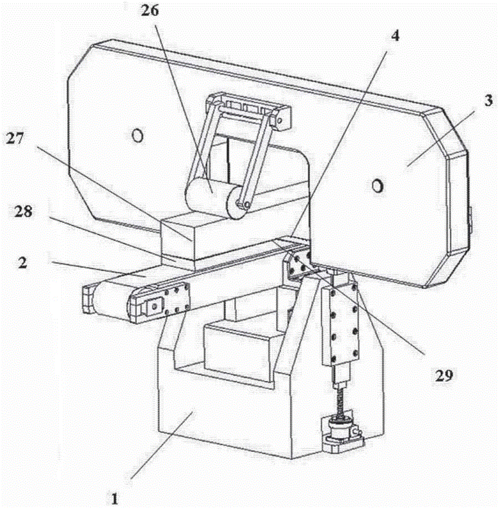
[0046] Use saw blade spacer of the present invention on vertical band saw machine (referring to Figure 4-6 ), the workbench and the sawing device are perpendicular to each other, the separator is arranged behind the saw blade, and a wedge-shaped knife edge 25 is provided near the side of the saw blade. The separator and the saw blade are aligned and arranged on the same vertical plane. The separator The two ends of the separator are connected with the shell of the sawing device, and one end of the separator is fixedly connected with the first fixing device through the first fastening adjusting bolt 15 arranged in the first connecting hole, and the other end of the separator is connected with the second fixing device. The device forms a movable and adjustable connection through the first fastening and adjusting bolt 15 arranged in the second connection hole 12. One side of the second tensioning and fixing device is provided with a tensioning device. The tensioning device consis...

Embodiment 2

[0049] Use the saw blade spacer of the present invention on a horizontal band saw machine (see Figure 7-10 ), the workbench and the sawing device are parallel to each other, the separator is arranged behind the saw blade, and a wedge-shaped knife edge 25 is provided near the side of the saw blade. The separator and the saw blade are arranged on the same horizontal plane, and the two ends of the separator The shell of the device is connected, and one end of the separator is fixedly connected with the first fixing device through the first fastening adjustment bolt 15 arranged in the first connection hole, and the other end of the separator is provided with a group of elongated adjustment holes 11, separating The other end of the sheet and the second fixing device form a movably adjustable connection through the first fastening adjustment bolt 15 arranged in the second connection hole 12, and the tension degree and effective working length of the entire partition board are determ...


PUM


Abstract

The invention relates to a saw blade separation device for a band sawing machine. The saw blade separation device for the band sawing machine is characterized in that a working table and a sawing device are arranged perpendicularly or in parallel; a saw blade separation piece is arranged behind a saw blade; the separation piece and the saw blade are arranged on the same horizontal plane; the separation piece and the sawing device are connected; and one end of the separation piece is fixedly connected with the sawing device, and the other end of the separation piece and the sawing device form a movable adjusting connection. When the saw blade separation device for the band sawing machine is used, because of existence of the separation piece, the saw blade generates no saw clamping phenomenon during sawing, and is not easy to wear; a domestic cheap saw blade can be adopted; meanwhile, the batch high-precision double-surface planing has no need to be performed beforehand for wood before machining, and the sawing can be directly performed, so that the machining cost is reduced; and a pressing wheel above the working table of the horizontal band sawing machine can tightly press the wood, so that a sawn plate is more smooth, the machining thickness of the plate is not limited, and the application range of the band sawing machine is wider.

Description

technical field [0001] The invention relates to the technical field of band saw machines, in particular to a saw blade partition device for horizontal or vertical band saw machines. Background technique [0002] For a long time, when the woodworking band saw machine is processing and sawing wood panels, the wood block is driven by the motor to drive the flywheel of the band saw machine to rotate the saw blade to saw the wood. (see figure 1 Mark 29), the stress inside the wood square material changes suddenly, causing the boards on both sides of the sawing road to be easily twisted and deformed during the sawing process, so the boards on both sides of the sawing kerf (see figure 1 Labels 27, 28) often clamp the saw blade in high-speed rotation (label 4), causing the rotating saw blade (see figure 1 Mark 4) due to double-sided plate (see figure 1 Labels 27 and 28) generate high temperature due to pinch sawing, resulting in changes in the material of the band saw blade. When...

Claims


Application Information

Patent Timeline
Patent Type & Authority Applications(China)
IPC IPC(8): B27B13/16
CPCB27B13/16
Inventor 张家铭张棋惠许倍嘉
Owner 张家铭
Why Eureka
Try Eureka