
Combustion heat exchange assembly and combustion heat exchange equipment

A technology of heat exchange components and heat exchange parts, applied in lighting and heating equipment, burners, combustion methods, etc., can solve problems such as high temperature deformation, influence on combustion effect, unreliable installation of preheating burner and catalytic burner, etc. Achieve the effect of high working reliability and good combustion effect

Pending Publication Date: 2021-07-20
WUHU MIDEA KITCHEN & BATH APPLIANCES MFG CO LTD +1
View PDF0 Cites 0 Cited by
  • Summary
  • Abstract
  • Description
  • Claims
  • Application Information

AI Technical Summary

Problems solved by technology

[0002] At present, some water heaters use the combination of preheating burner and catalytic burner to heat the water flowing through the heat exchanger, but the installation support structure of the preheating burner and catalytic burner is prone to high temperature deformation due to long-term high temperature environment. Leads to unreliable installation of preheat burners and catalytic burners
[0003] In addition, in order to meet a good combustion effect, a certain distance must be maintained between the preheating burner and the catalytic burner. During the use of existing water heaters, due to the high-temperature deformation of the installation support structure, the preheating burner and catalytic burner It is difficult to keep the distance between them constant, which will affect the combustion effect

Method used


Image

  • Combustion heat exchange assembly and combustion heat exchange equipment
  • Combustion heat exchange assembly and combustion heat exchange equipment
  • Combustion heat exchange assembly and combustion heat exchange equipment

Examples


Embodiment Construction

[0030] Embodiments of the present invention are described in detail below, examples of which are shown in the drawings, wherein the same or similar reference numerals designate the same or similar elements or elements having the same or similar functions throughout. The embodiments described below by referring to the figures are exemplary and are intended to explain the present invention and should not be construed as limiting the present invention.

[0031] In describing the present invention, it should be understood that the terms "longitudinal", "transverse", "length", "width", "thickness", "upper", "lower", "front", "rear", " The orientation or positional relationship indicated by "left", "right", "vertical", "horizontal", "top", "bottom", "inner", "outer", etc. is based on the orientation or positional relationship shown in the drawings, It is only for the convenience of describing the present invention and simplifying the description, but does not indicate or imply that ...


PUM


Abstract

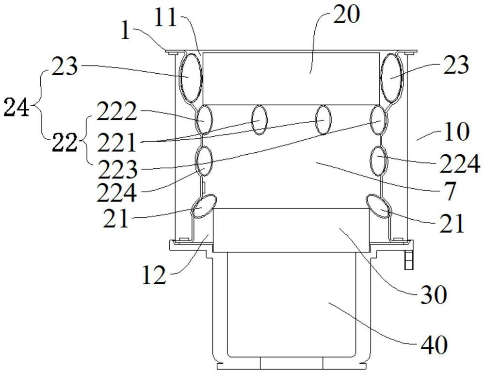
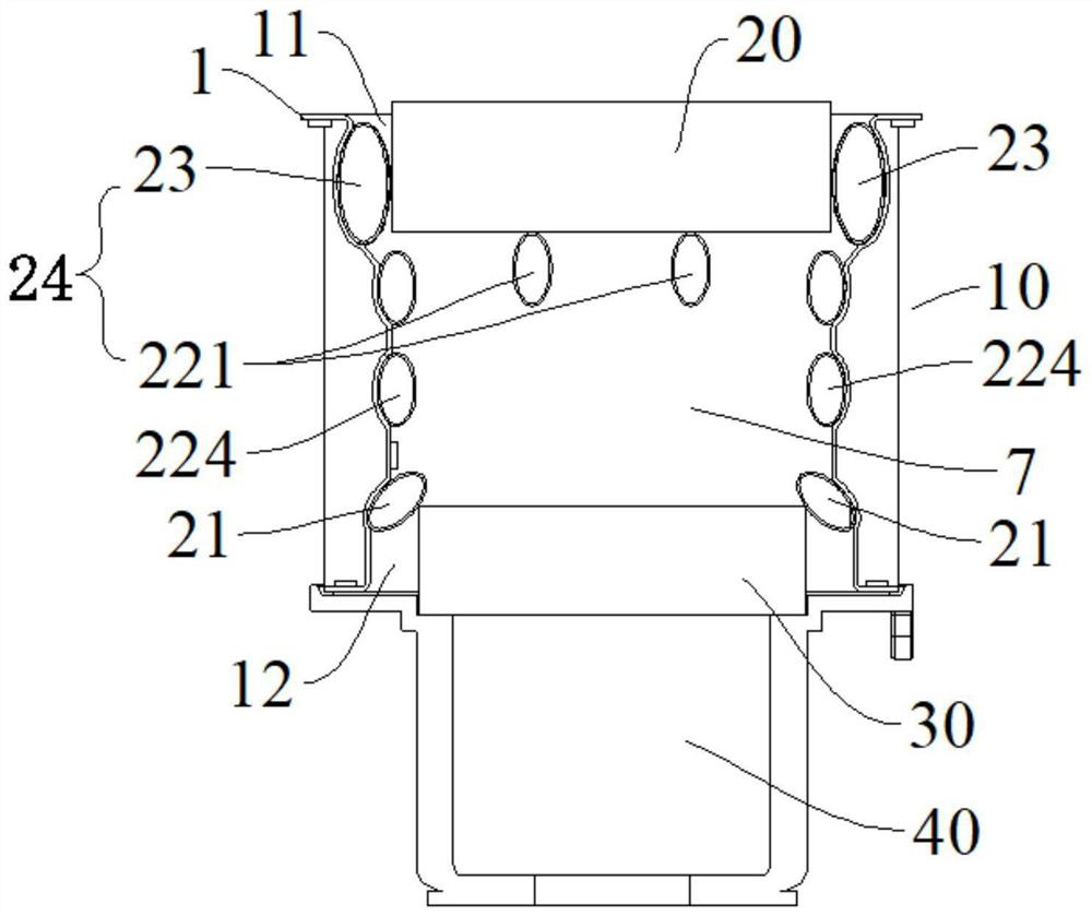
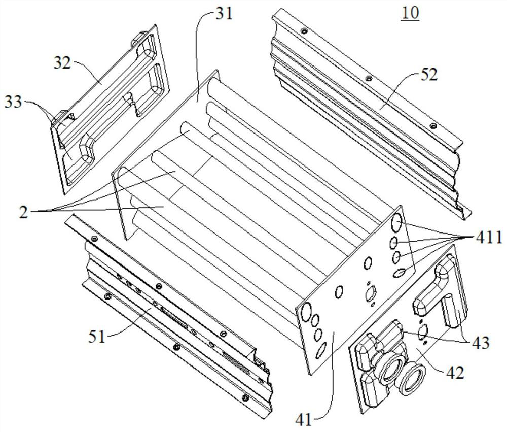
The invention discloses a combustion heat exchange assembly and combustion heat exchange equipment. The combustion heat exchange assembly comprises a heat exchanger, wherein the heat exchanger is provided with a shell, and a heat exchange part is arranged in the shell; a heat exchange medium channel is formed in the heat exchange part, an upper catalytic combustor mounting space and a lower preheating combustor mounting space are formed in the shell, and the heat exchange part comprises an mounting heat exchange part and stop heat exchange parts; and a catalytic combustor is at least partially arranged in the catalytic combustor mounting space and is limited by the mounting heat exchange part, and a preheating combustor is at least partially arranged in the preheating combustor mounting space and is stopped and limited by the stop heat exchange parts. According to the combustion heat exchange assembly, the stop heat exchange parts and the mounting heat exchange part are less affected by high temperature and do not deform at high temperature, so that the problem that a preheating combustor and a catalytic combustor cannot be mounted and fixed due to the fact that a common mounting support deforms at high temperature is solved; and meanwhile, the distance between the preheating combustor and the catalytic combustor is not prone to change, so that a good combustion effect is favorably ensured.

Description

technical field [0001] The invention relates to the technical field of water heaters, in particular to a combustion heat exchange assembly and combustion heat exchange equipment. Background technique [0002] At present, some water heaters use a combination of preheating burner and catalytic burner to heat the water flowing through the heat exchanger, but the installation support structure of the preheating burner and catalytic burner is prone to high temperature deformation due to long-term high temperature environment, Lead to unreliable installation of preheat burner and catalytic burner. [0003] In addition, in order to meet a good combustion effect, a certain distance must be maintained between the preheating burner and the catalytic burner. During the use of the existing water heater, due to the high-temperature deformation of the installation support structure, the preheating burner and the catalytic burner The distance between them is difficult to keep constant, wh...

Claims


Application Information

Patent Timeline
Patent Type & Authority Applications(China)
IPC IPC(8): F24H9/18F24H9/20F23D14/02F23D14/62
CPCF23D14/02F23D14/62F24H9/1836F24H9/2035
Inventor 李茂照黄官贤刘继锋梁国荣
Owner WUHU MIDEA KITCHEN & BATH APPLIANCES MFG CO LTD
Learn More