Pinned cylindrical roller bearing

a cylindrical roller bearing and roller bearing technology, applied in the direction of bearings, shafts and bearings, bearing components, etc., can solve the problems of affecting the bearing configuration, and creating axial loads or amplifying existing axial loads

Active Publication Date: 2021-05-25
ENGINEERED BEARING TECH INC
View PDF3 Cites 0 Cited by
  • Summary
  • Abstract
  • Description
  • Claims
  • Application Information

AI Technical Summary

Benefits of technology

[0015]The alternating threaded hole configuration providing alternating threaded ends of the pins in the first and second support rings of the bearing assembly can provide advantages which include, but are not limited to: increased stability of the bearing, reduced skewing of the pins, reduced warping of a component of the bearing assemblies, reduced load on the other pump components, longer life for the bearing or pump, and the like.
[0017]In one embodiment of the invention, the roller pin is unthreaded at both ends, and comprises a shouldered configuration at both ends, wherein the shouldered, unthreaded pins are countersunk with a support ring of a bearing assembly and hot-riveted into position. The, although shouldered pins are known, the countersunk shouldered pins can provide an advantage during assembly of a roller bearing. Specifically, known shouldered bearings are not configured for countersinking with a support ring, and are only abutted to an outer surface of the support ring so the support ring and shouldered pin are in flush contact. By countersinking the shouldered pin with the support ring, the pins and rollers are more stably positioned during assembly and facilitate positioning of the pin and roller in a perpendicular position relative to the support ring.

Problems solved by technology

However, a major and persistent problem resulted from these conventional roller bearings using the pinned cylindrical roller configuration, namely, that the pinned roller bearings created axial load or amplified the existing axial load on the crankshaft of the pump motor.
This amplification of the axial load resulted in the crankshaft being pushed in a corkscrew fashion, which ultimately drove the crankshaft out of the pump and causing failure of the pump.
Cold riveting the pins into place in the bearing assembly has a tendency to bend the roller pin tip instead of creating a pin head.
The heat generated in the welding process can warp the support ring, the pin, or the bearing race, thus altering the configuration of the bearing.

Method used


Image

  • Pinned cylindrical roller bearing
  • Pinned cylindrical roller bearing
  • Pinned cylindrical roller bearing

Examples


Embodiment Construction

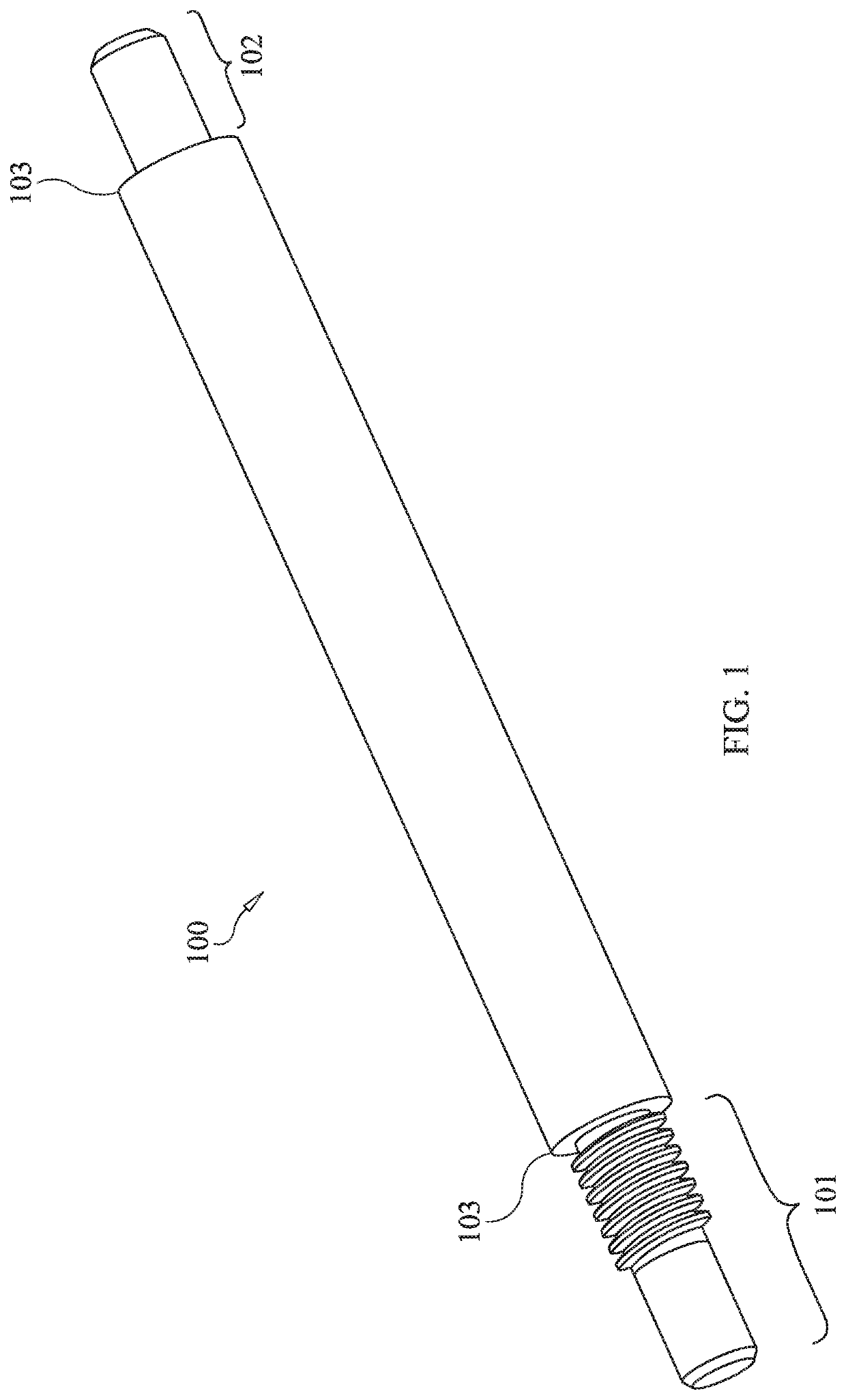
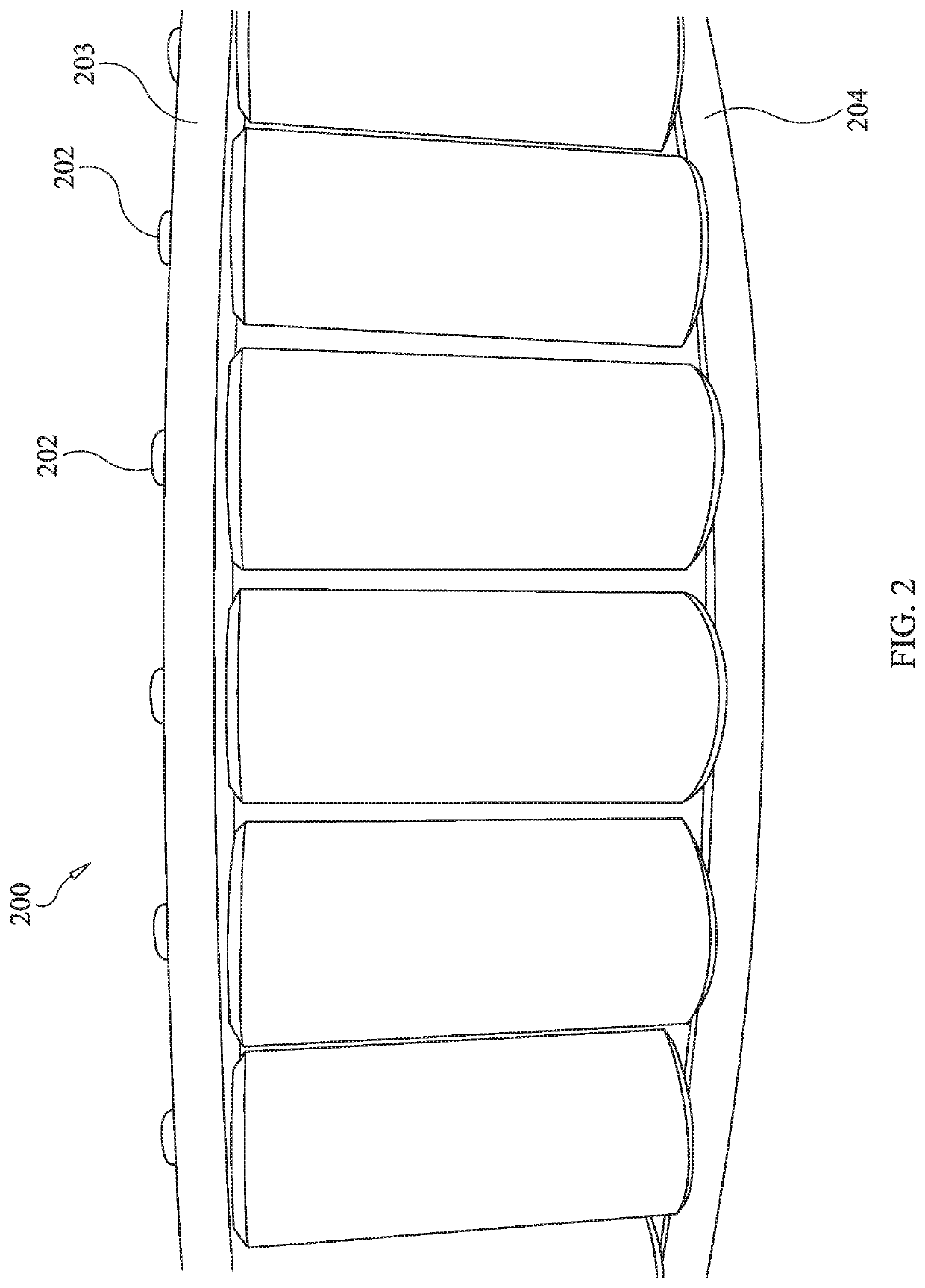
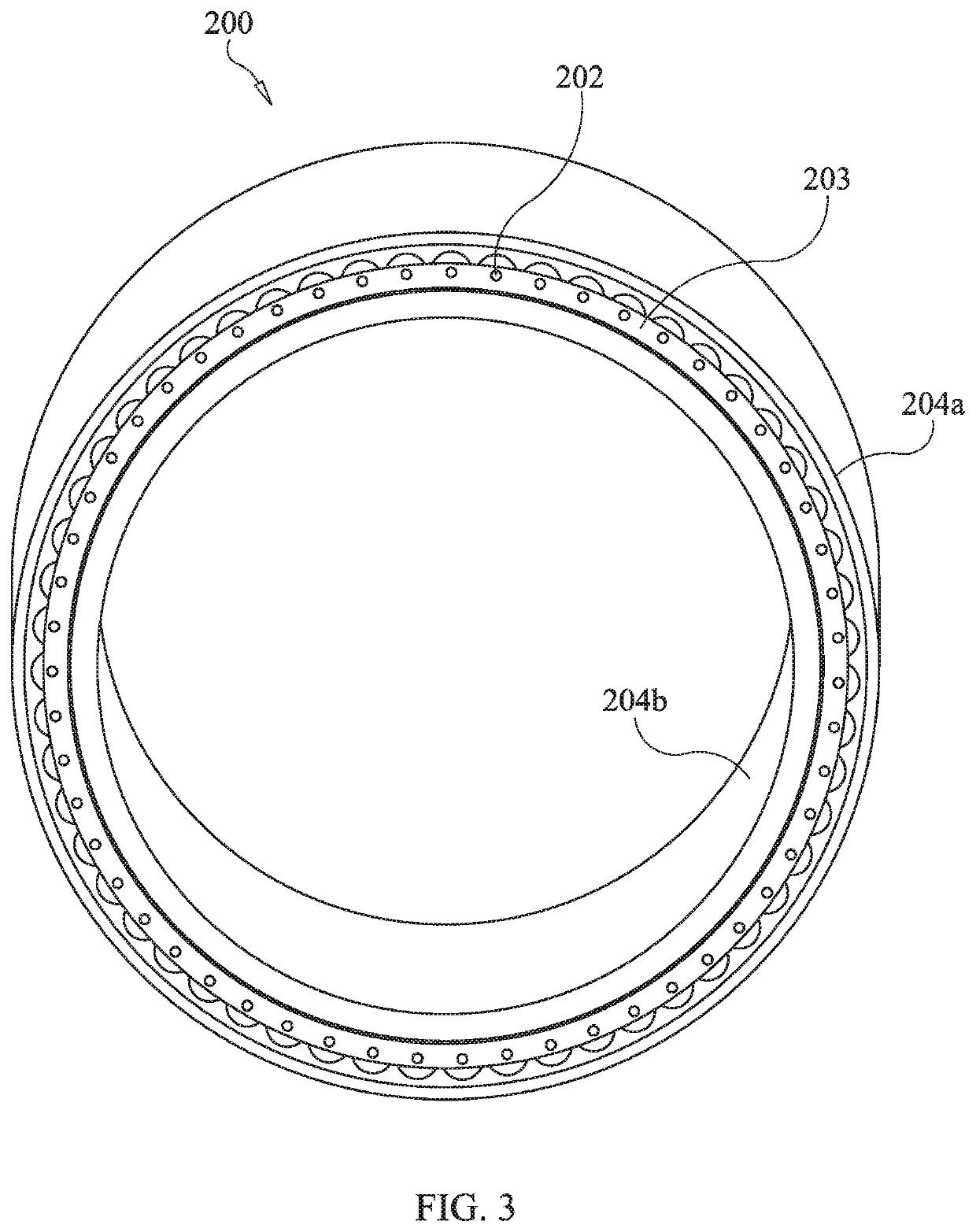
[0029]All roller bearings used for mechanical motors, such as pump motors, comprise a first (e.g., inner) and second (e.g., outer) circular race having cylindrical rollers disposed perpendicularly in relation to plane of the race. A traditional roller bearing comprises a cage machined to be close-fitting to align and guide the rollers to reduce skewing. Due to problems caused by axial forces on the rollers used in traditional roller bearings, improved (now conventional) roller bearings were manufactured to include pins disposed through the central longitudinal axis of the roller, and affixed to the cage by cold riveting or welding. These conventional pin roller bearings were also less than ideal because, although the axial forces on the rollers were reduced, forces were transferred to the bearing itself, or to the crankshaft, causing failure of the pump.

[0030]Unexpectedly, by threadingly engaging one end of a roller bearing pin to at least one of the two support rings disposed on ea...


PUM

PropertyMeasurementUnit
temperaturesaaaaaaaaaa

Abstract

A pinned roller bearing assembly having a plurality of pinned rollers, wherein each of the pins has a first threaded end received in a threaded aperture of a first support ring, and a second unthreaded and shouldered end received in a countersunk and unthreaded aperture of a second support ring. Each end of each pin extends through its respective support ring and is rivetingly domed outside the support ring to secure its position and configuration. The pinned roller bearings and support rings are disposed within an outer and inner race.

Description

BACKGROUND OF THE INVENTION[0001]In traditional spherical or cylindrical roller bearings for use in mechanical pumps and other mechanical motors or engines, close-fitting machined cages, or races, were employed to align and guide rollers, thereby reducing skewing of the rollers. This traditional configuration for alignment and guidance of the rollers reduced the number of rollers that could be provided in the bearing, and thereby reduced the basic radial rating of the bearing. This traditional configuration also translated into axial loading on the roller generated by the bearing itself.[0002]To reduce the axial load on the cylindrical roller, and to increase and optimize the number of rollers within the cage, a bearing was designed having a pin which extended through the axial center, or longitudinal midline, of the cylindrical roller, wherein the pin was affixed at each end to support rings of the cage assembly.[0003]This “pinned roller” configuration became the conventional desig...

Claims


Application Information

Patent Timeline
Patent Type & Authority Patents(United States)
IPC IPC(8): F16C13/02F16C19/26F16C43/06B23P15/00F16C33/52
CPCF16C13/02B23P15/003F16C19/26F16C33/526F16C43/06B23P11/005F16C33/523F16C43/065
Inventor HARRISON, CURTIS
Owner ENGINEERED BEARING TECH INC
Why Eureka
Try Eureka