Positioning bearing structure for device

A device and positioning technology, applied in the field of positioning and storage structures, can solve the problems of poor device storage stability and low space utilization, and achieve the effects of improving storage stability, avoiding fixed drawer sizes, and improving user experience.

Pending Publication Date: 2021-03-09
GUANGDONG DTC HARDWARE PRECISION MFG CO LTD
View PDF1 Cites 0 Cited by
  • Summary
  • Abstract
  • Description
  • Claims
  • Application Information

AI Technical Summary

Problems solved by technology

[0003] The purpose of the present invention is to provide a positioning and holding structure for devices, to overcome the fixed size of the drawer in the prior art, which can only hold devices of a single size, the space utilization rate is low, and the stability of device holding is poor inadequacies of

Method used


Image

  • Positioning bearing structure for device
  • Positioning bearing structure for device
  • Positioning bearing structure for device

Examples


Embodiment Construction

[0034] The present invention will be further described below in conjunction with the accompanying drawings and embodiments.

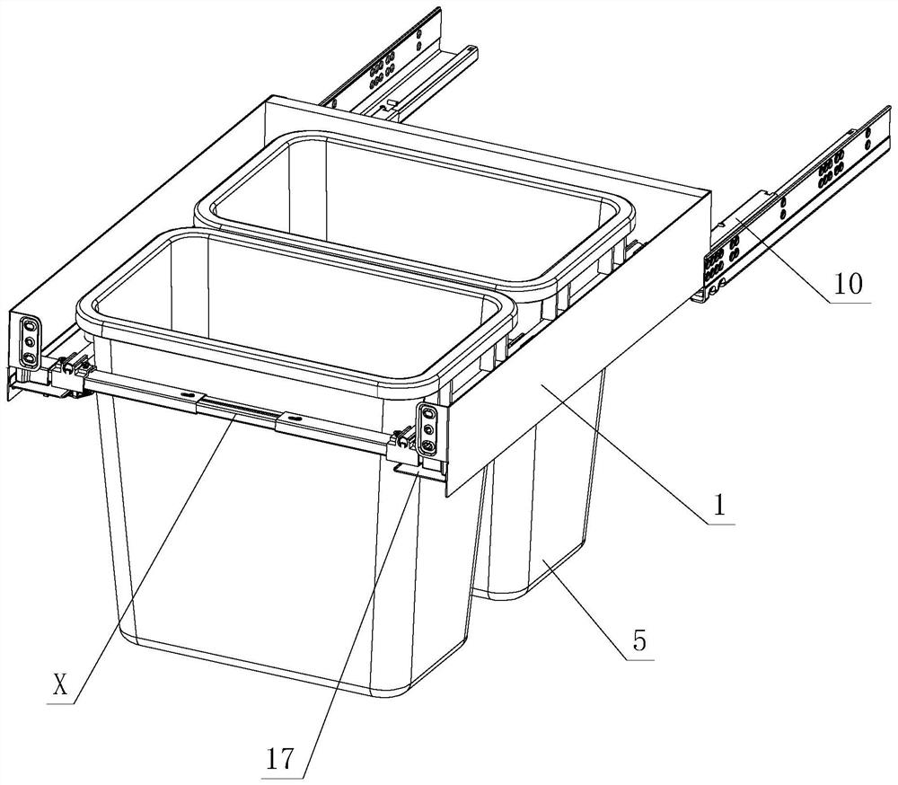
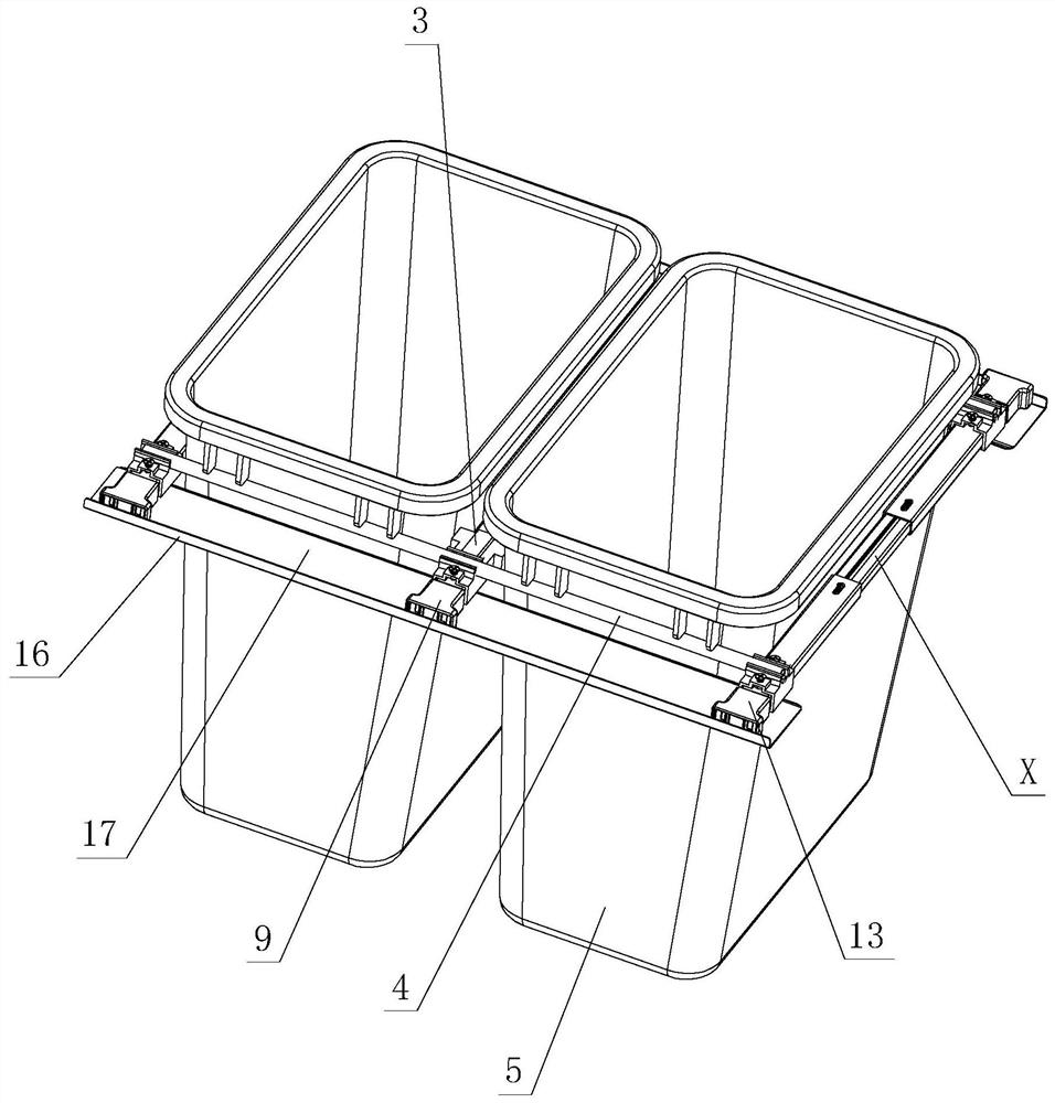
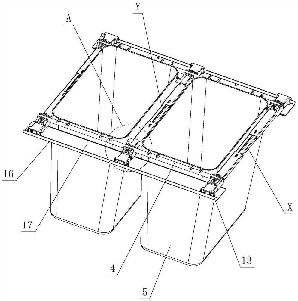
[0035] see Figure 1-Figure 8 , which is used for the positioning and receiving structure of the device, including side plates 1 arranged on the left and right, left and right supporting parts are respectively arranged on the bottom of the left and right side plates 1, and a receiving device is arranged between the left and right supporting parts, and the receiving device includes at least three The front, middle and rear cross-bar telescopic components arranged in the front, middle and rear and can be positioned and moved laterally, wherein, the front and rear cross-bar telescopic components X have front and rear movable parts 2 for lateral movement respectively, and the middle cross-bar telescopic component Y has middle movable parts for lateral movement Part 3, and connecting rod 4 is also arranged between the front, middle and rear movable parts.

...


PUM


Abstract

The invention discloses a positioning bearing structure for a device. The structure comprises a left supporting part and a right supporting part which are arranged on the lower portion of a left sideplate and the lower portion of a right side plate respectively, a bearing device is arranged between the left supporting part and the right supporting part and comprises a front transverse rod telescopic assembly, a middle transverse rod telescopic assembly and a rear transverse rod telescopic assembly, front and back movable pieces transversely move on the front transverse rod telescopic assemblyand the middle transverse rod telescopic assembly respectively, and a middle movable piece transversely moves on the middle transverse rod telescopic assembly; connecting rods are arranged among thefront, middle and rear movable pieces; the middle transverse rod telescopic assembly and the middle movable piece synchronously and longitudinally slide between the front and rear transverse rod telescopic assemblies through the connecting rods; at least two containing devices and a bearing area with the adjustable longitudinal and / or transverse size are formed between the front, middle and rear transverse rod telescopic assemblies and the front, middle and rear movable pieces when the assemblies and movable pieces move. Limiting parts are arranged on the front side and the rear side of the middle movable piece. And the at least two devices are positioned and placed on the bearing area in a suspended mode, and the at least two devices are mutually limited through the limiting parts of themiddle movable piece when being placed. Through the improvement of the structure, the practicability is high.

Description

technical field [0001] The invention relates to a positioning and accommodating structure for devices. Background technique [0002] The Chinese patent document number is CN111086803A, which discloses a drawer-type concealed trash can on May 1, 2020, which includes a trash can, a flat panel, a drawer guide rail and a connecting device, and the connecting device is either an L-shaped corner code or a wooden strip. It is said that the above-mentioned structure combines the trash can, flat panel and drawer guide rails into one. Usually the trash can is hidden in the vacant space under the furniture floor, and it is pulled out when it is needed, which eliminates the stumbling and unsightlyness of the trash can placed in the room Two big disadvantages; however, the size of the space in the kitchen is different, and the size of the drawers is designed according to the space in the kitchen. The size of the trash can is concealed, its use is limited, and its flexibility is poor. M...

Claims


Application Information

Patent Timeline
Patent Type & Authority Applications(China)
IPC IPC(8): A47B77/18B65F1/14
CPCA47B77/18B65F1/141
Inventor 伍志勇
Owner GUANGDONG DTC HARDWARE PRECISION MFG CO LTD
Why Eureka
Try Eureka