
Turbocharger having a thermal dam

a technology of thermal dam and turbine, which is applied in the direction of sliding contact bearings, mechanical equipment, machines/engines, etc., can solve the problems of increased vehicle emissions, increased heat transfer, and failure of turbines, so as to reduce heat transfer, reduce heat transfer, and increase compressor performance

Active Publication Date: 2022-01-04
BORGWARNER INC
View PDF19 Cites 0 Cited by
  • Summary
  • Abstract
  • Description
  • Claims
  • Application Information

AI Technical Summary

Benefits of technology

The patent describes a design for a turbocharger that reduces heat transfer to other components in the bearing housing and increases compressor performance. This is achieved by having a thermal dam with a smaller second diameter and a smaller axial distance from the turbine wheel. The design also allows the turbocharger to reach target temperatures without water cooling.

Problems solved by technology

However, the exhaust flow used to spin the turbine wheel is very hot which in turn leads to components of the bearing housing adjacent to the turbine wheel also getting hot, which can cause turbocharger failure.
However, water cooling requires additional components in the bearing housing.
Further, the used hot water from the water cooling produces waste heat which can lead to higher vehicle emissions.

Method used


Image

  • Turbocharger having a thermal dam
  • Turbocharger having a thermal dam
  • Turbocharger having a thermal dam

Examples


Embodiment Construction

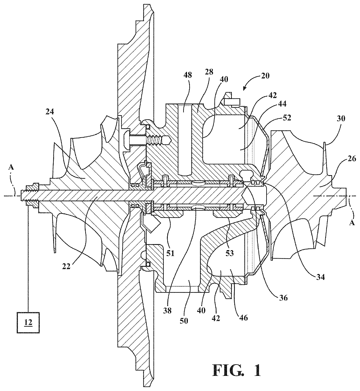
[0015]With reference to the Figures, wherein like numerals indicate like parts throughout the several views, a turbocharger 20 is generally shown in FIG. 1. The turbocharger 20 is coupled to a vehicle engine 12 such as an internal combustion engine 12, however, it is contemplated that the vehicle engine may be any type of power generator including but not limited to an electric motor, a battery, or a fuel cell. The turbocharger 20 receives exhaust gas from the internal combustion engine 12 and delivers compressed air to the internal combustion engine 12.

[0016]Although not required, the turbocharger 20 is typically used in passenger and commercial automotive applications. However, it is to be appreciated that the turbocharger 20 may be used in non-automotive applications such as heavy equipment applications, non-automotive diesel engine applications, non-automotive motor applications, and the like.

[0017]With reference again to FIG. 1, the turbocharger 20 typically includes a turbocha...


PUM


Abstract

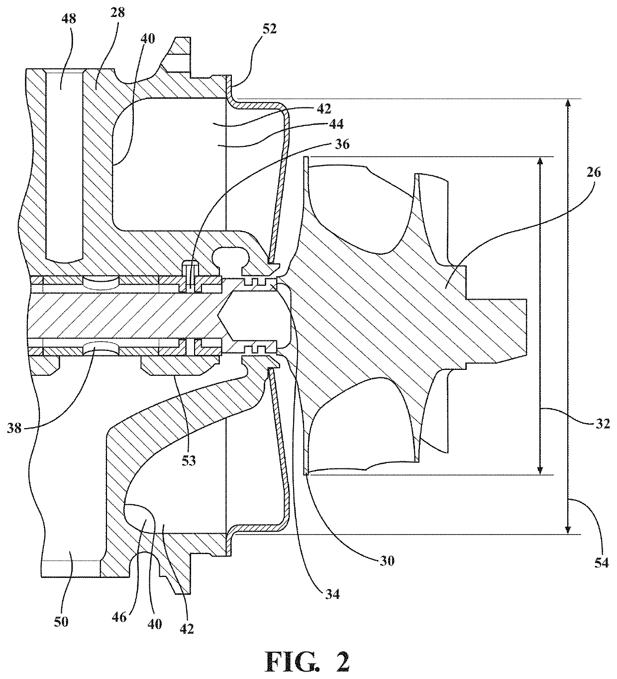
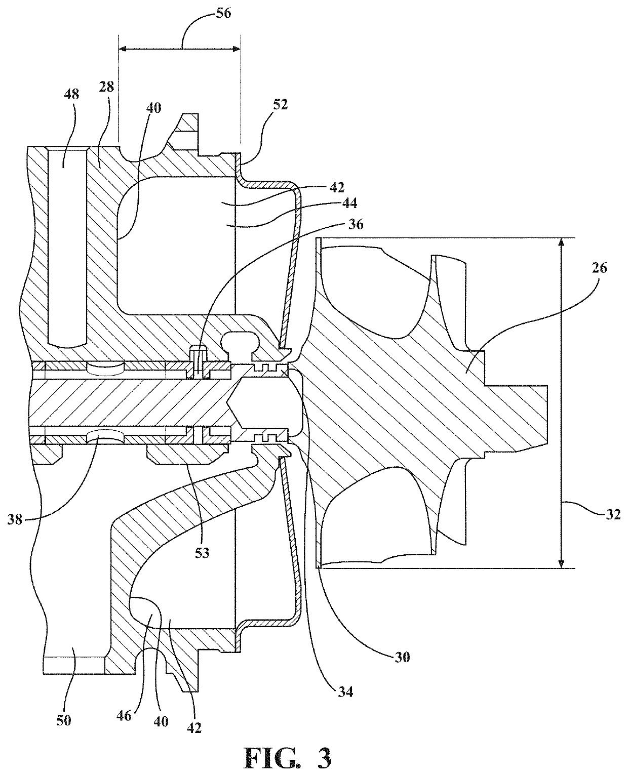
A turbocharger includes a shaft extending along an axis, a compressor wheel coupled to a first end of the shaft, a turbine wheel coupled to a second end of the shaft and having a first diameter; and a bearing housing extending about the shaft. The bearing housing is disposed between the compressor wheel and the turbine wheel. The bearing housing having a thermal dam having a volume extending circumferentially about the shaft and disposed proximate to the second end of the shaft between the compressor wheel and the turbine wheel. The thermal dam has a second diameter extending radially from the shaft. Moreover, the second diameter of the thermal dam is between 1.1 and 1.2 times greater than the first diameter of the turbine wheel.

Description

BACKGROUND OF THE INVENTION1. Field of the Invention[0001]The present invention generally relates to a turbocharger and more particularly to a turbocharger having a thermal dam.2. Description of the Related Art[0002]Turbochargers include a turbine wheel, a compressor wheel coupled to the turbine wheel through a shaft, and a bearing housing extending about the shaft and disposed between the turbine wheel and the compressor wheel. Turbochargers use exhaust flow from an internal combustion engine and deliver compressed air to the internal combustion engine. More specifically, turbochargers use exhaust flow to spin the turbine wheel. The turbine wheel, in turn, rotates the shaft which rotates the compressor wheel to deliver the compressed air the internal combustion engine. However, the exhaust flow used to spin the turbine wheel is very hot which in turn leads to components of the bearing housing adjacent to the turbine wheel also getting hot, which can cause turbocharger failure.[0003...

Claims


Application Information

Patent Timeline
Patent Type & Authority Patents(United States)
IPC IPC(8): F02B33/40F02C6/12F01D25/16
CPCF02B33/40F01D25/16F02C6/12F05D2220/40F16C2360/24F05D2240/15F01D25/166F16C17/02F16C2202/20
Inventor CHANDRAMOHANAN, RAJ
Owner BORGWARNER INC
Learn More