Compression pipe fitting with wide range grip rings

a compression pipe and gripping technology, applied in the field of compression pipe fittings, can solve the problems undesirable pipe movement, and large fitting ends, and achieve the effects of less robust plastics, less corrosion resistance, and less metal-based manufacturing

Active Publication Date: 2021-05-25
A Y MCDONALD MFG CO
View PDF19 Cites 3 Cited by
  • Summary
  • Abstract
  • Description
  • Claims
  • Application Information

AI Technical Summary

Benefits of technology

[0012]In yet another form of this aspect of the disclosed compression fittings, a grip ring encircles the selected pipe, the grip ring having a surface engaging the fitting nut whereby axial movement of the fitting nut over the support body biases the grip ring radially inwardly toward the selected pipe. In a further form, the fitting nut at an axial end has a surface tapered to a reduced inner diameter around the selected pipe, and the grip ring has a sloped surface engaging the fitting nut tapered surface whereby axial movement of the fitting nut when threaded onto the end section threaded outer surface biases the grip ring radially inwardly toward the selected pipe. In a still further form, the grip ring has an outer annular spine with radially inwardly extending sides, the fitting nut has a minimum diameter at its end engaging the grip ring, and when the grip ring is biased inwardly against the selected pipe, the grip ring spline and sides have a minimum radial height which is greater than half of the difference between the minimum fitting nut diameter and the outer diameter of the selected pipe. In a yet further form, cuts through the grip ring sides facilitate bending of the grip ring into engagement with the outer diameter of the selected pipe.
[0017]In still another aspect of the disclosed advantageous compression fittings for connecting a selected one of pipes having a range of outer diameters between a maximum diameter and a minimum diameter, a support body is substantially tubular around an axis with an inner surface having a selected inner diameter, the support body having a face on at least one axial end tapered outwardly from the support body inner surface, the end face being substantially conical along and around the axis. At least one gasket is adapted to fit over the selected pipe, and at least one fitting nut is movable axially over the support body to a compression fitting position. A grip ring encircles the selected pipe and engages the fitting nut whereby axial movement of the fitting nut toward the compression fitting position biases the grip ring radially inwardly toward the selected pipe. A blocking member is around the selected pipe and adjacent the support body tapered end, whereby axially moving the fitting nut draws the support body axially toward the grip ring and biases the gasket radially inwardly against the selected pipe, and the blocking member blocks any gap between the pipe outer diameter and the support body inner surface to prevent unloading of the gasket.
[0023]In yet another form of this aspect of the disclosed compression fittings, the grip ring in transverse cross-section has a V-shape with the point of the V facing away from the pipe and the ends of the legs of the V biased toward the pipe. In a further form, the ends of the radially inwardly extending legs of the V-shaped grip ring are pointed whereby the pointed leg ends dig into the outer diameter of the selected pipe to anchor the grip ring in the axial direction to the selected pipe. In another further form, cuts through the grip ring in an axial direction, the cuts facilitating bending of the grip ring into engagement with the outer diameter of the selected pipe.
[0027]In yet another aspect of the disclosed advantageous compression fittings for connecting a selected one of pipes having a range of outer diameters between a maximum diameter and a minimum diameter, a support body is substantially tubular around an axis with an inner surface having a selected inner diameter, the support body having a face on at least one axial end. At least one gasket is adapted to fit over the selected pipe, and at least one fitting nut is adapted to move axially relative to the support body, the fitting nut at its axial end having an end surface tapered to a reduced inner diameter around the selected pipe. A grip ring encircles the selected pipe and engages the fitting nut whereby axial movement of the fitting nut onto the support body biases the grip ring radially inwardly toward the selected pipe. A blocking member is around the selected pipe and adjacent the support body end face, whereby axially moving the fitting nut to a compression fitting position draws the support body and the grip ring together in the axial direction and loads the gasket to bias the gasket inward radially against the selected pipe, and the blocking member blocks any gap between the pipe outer diameter and the support body inner surface to prevent unloading of the gasket.

Problems solved by technology

If incorrect pipes with smaller diameters are installed with a fitting intended for larger diameter pipes, the grip ring may not engage the pipe and the rubber gasket will tend to escape through the gap between the pipe and internal fitting walls.
The resulting unloaded gasket may not maintain the desired seal around the pipe (resulting in fluid leaks) and also will not compress the grip ring (resulting in undesirable pipe movement).
Fittings have also been used which may accommodate a range of pipe diameters, utilizing grip rings and oversized gaskets which are less likely to escape from the fitting under load but result in physically larger fitting ends which are more expensive when made from metal, or less robust when made from plastics.

Method used


Image

  • Compression pipe fitting with wide range grip rings
  • Compression pipe fitting with wide range grip rings
  • Compression pipe fitting with wide range grip rings

Examples


Embodiment Construction

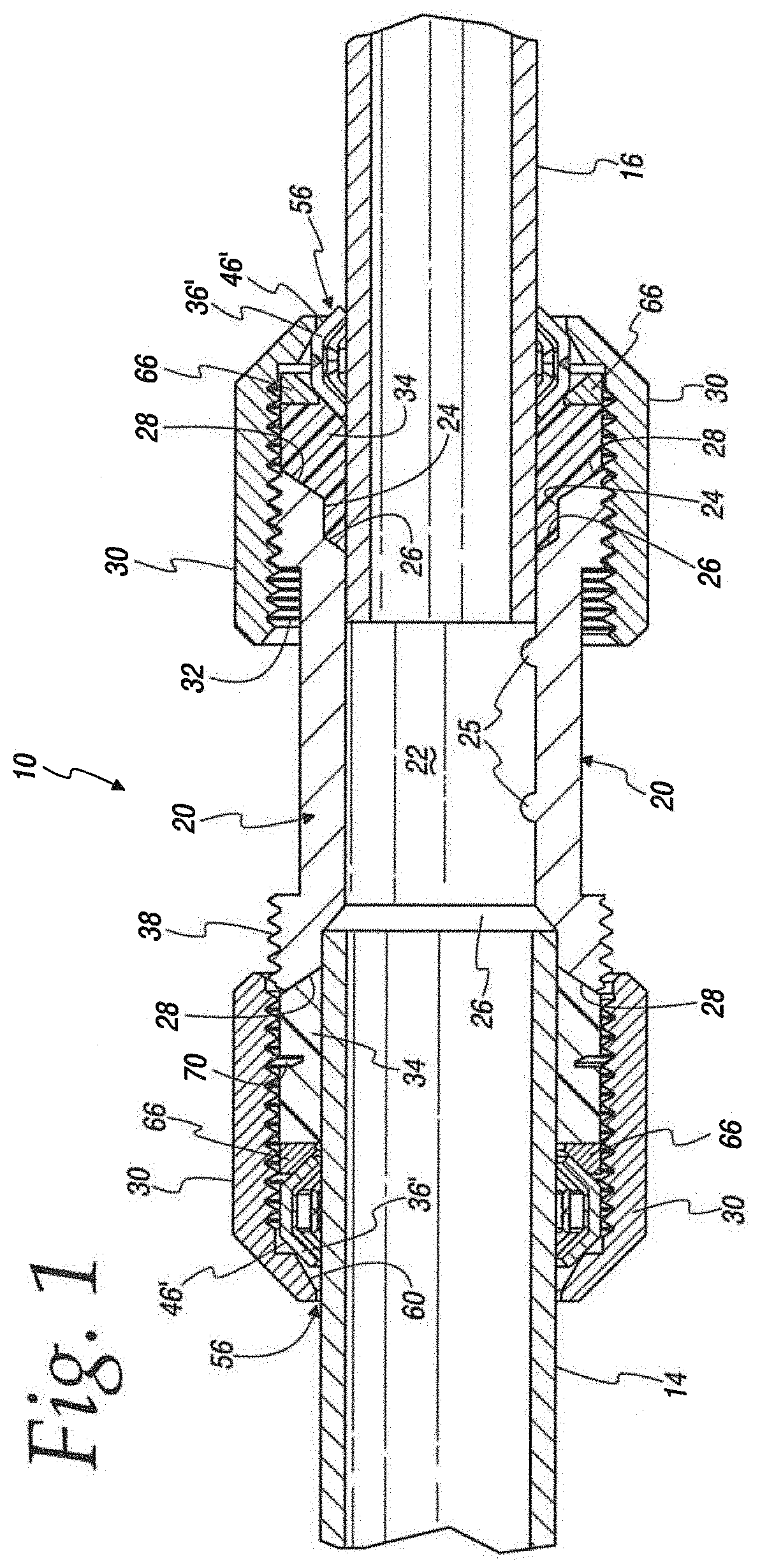
[0051]FIG. 1 illustrates one advantageous fitting 10 able to connect pipes of varying dimensions. Specifically, as illustrated, the fitting 10 connects a large diameter pipe 14 to a small diameter pipe 16 by use of, inter alia, a coupling body or internal gasket support body 20. As used herein and claimed, it should appreciated that references to “pipes” include piping and / or tubing systems (which contain, e.g., fluids and / or gases), conduits (which contain, e.g., electric wires, etc.) and the like.

[0052]The support body 20 is generally tubular with a round stepped interior consisting of a central body section or step 22 between end steps 24. The central step 22 has an internal diameter which is less than the internal diameter of the end steps 24. Stops 25 may optionally be provided in the inner surface of the central step 22 to limit movement of minimum radius pipes into the coupling or support body 20. Tapered or sloped sections 26 provide a stepped transition between the central ...


PUM


Abstract

Compression fittings for pipes having a range of diameters, including a support body with a central section between end sections, the central section having a smaller diameter than the end sections, with a transition surface between the central section and each end section. A gasket fits over a pipe and engages one of the support body end section end surfaces. A fitting nut is movable axially over the support body to draw the support body and the gasket together in the axial direction and bias the gasket radially inward against the pipe. A grip ring encircles the pipe at one gasket end and has a surface engaging the fitting nut whereby the fitting nut biases the grip ring radially inwardly toward the pipe. An insert adapter has a hub with a radially extending flange may block the other gasket end to load the gasket between its axial ends.

Description

CROSS-REFERENCE TO RELATED APPLICATIONS[0001]This application claims the benefit of the filing date of U.S. Provisional Ser. No. 62 / 479,928, filed Mar. 31, 2017, and U.S. Provisional Ser. No. 62 / 479,990, filed Mar. 31, 2017, the disclosures of which are hereby incorporated by reference in their entirety.FEDERALLY SPONSORED RESEARCH OR DEVELOPMENT[0002]Not Applicable.MICROFICHE / COPYRIGHT REFERENCE[0003]Not Applicable.FIELD OF THE INVENTION[0004]This invention relates to fittings used to connect piping or tubing systems which contain fluids, gases, or conduits which contain electric wires.BACKGROUND OF THE INVENTION[0005]Existing compression pipe fittings used for connecting pipes which are designed with grip rings are typically supported and driven closed by rubber gaskets. These fittings are also typically designed for one diameter or pipe material. If incorrect pipes with smaller diameters are installed with a fitting intended for larger diameter pipes, the grip ring may not engage...

Claims


Application Information

Patent Timeline
Patent Type & Authority Patents(United States)
IPC IPC(8): F16L19/12F16L19/10F16L25/14F16L19/075F16L19/08F16L19/06
CPCF16L19/12F16L19/075F16L19/086F16L19/103F16L19/106F16L25/14F16L19/061
Inventor LARSON, RYAN F.HAST, THOMAS W.
Owner A Y MCDONALD MFG CO
Why Eureka
Try Eureka