
Woven webbing combining edge and body weave design features for improved overall durability in lifting and restraint applications

a weave design and overall durability technology, applied in the field of tiedowns or slings, can solve the problems of increasing the cost of manufacturing straps or slings, straps being less desirable to handle once damaged, straps being cut, tear or broken, etc., to improve the cut resistance of tubular edges, improve the abrasion and edge cutting resistance, and improve the effect of cutting resistan

Active Publication Date: 2021-06-01
ELEVATOR ALL
View PDF11 Cites 1 Cited by
  • Summary
  • Abstract
  • Description
  • Claims
  • Application Information

AI Technical Summary

Benefits of technology

[0004]An object of the invention is to provide a woven product, such as, but not limited to, a tiedown or sling for lifting, restraint or other material handling functions which has improved abrasion and edge cutting resistance.
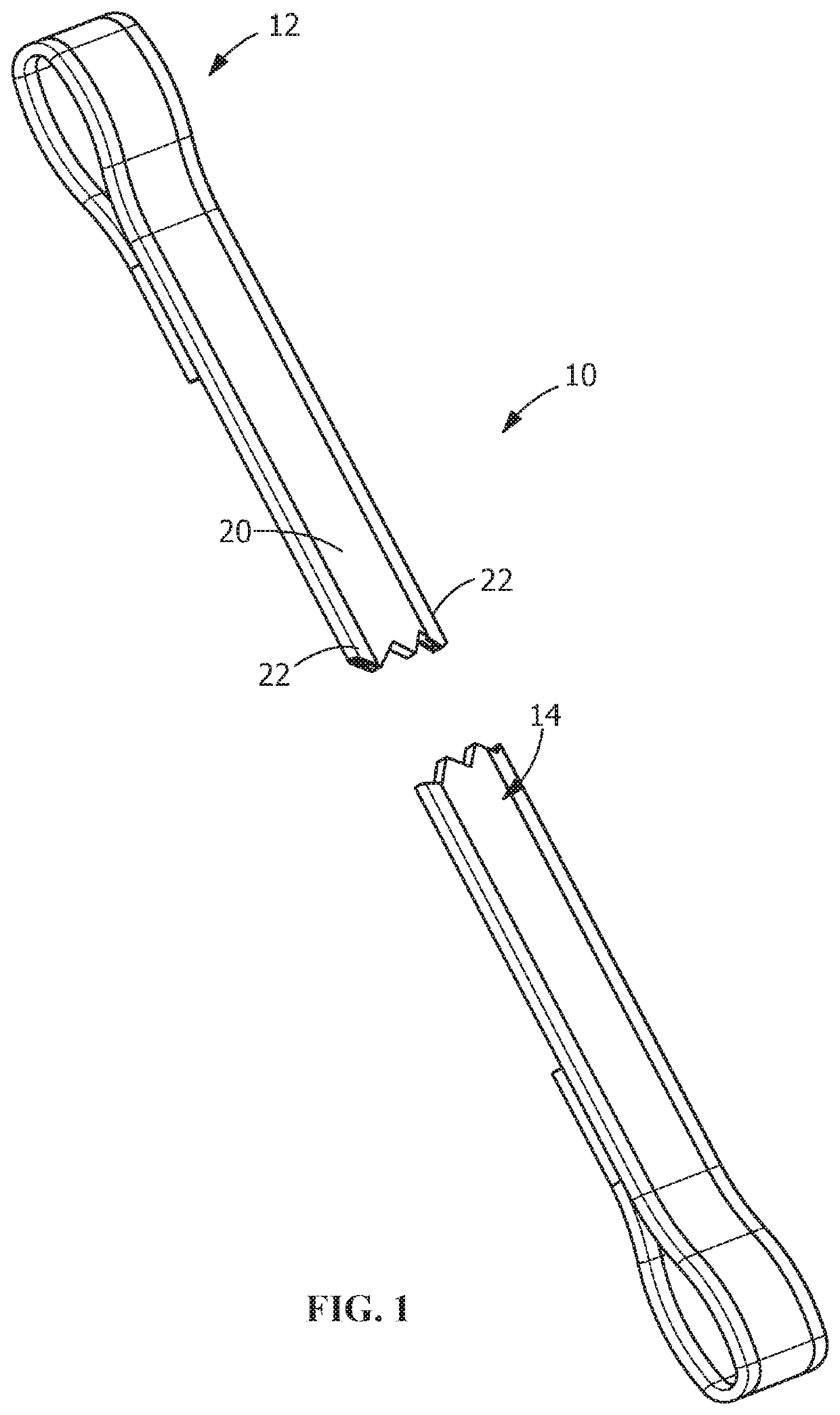
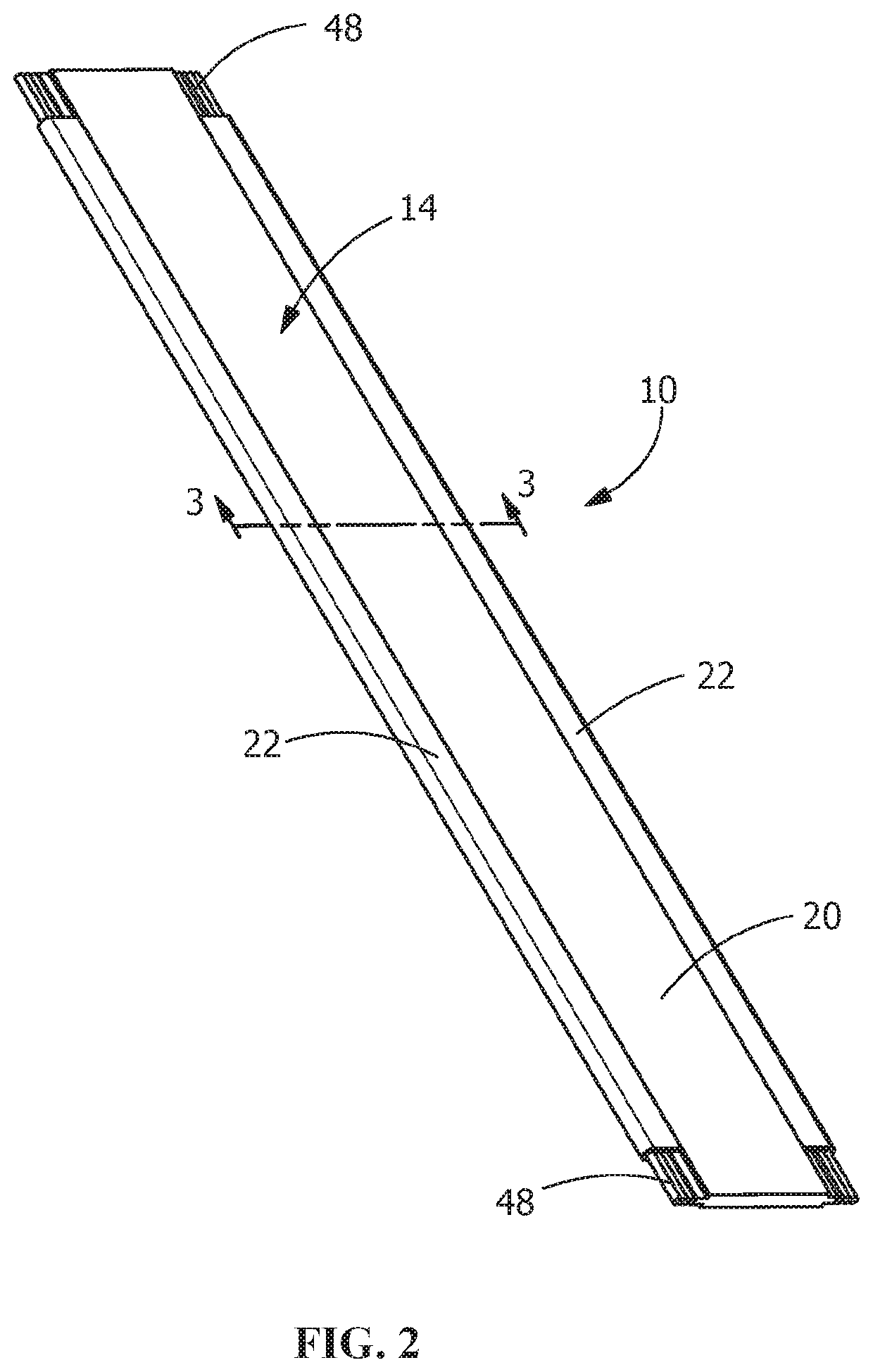
[0005]An embodiment is directed to a woven webbing for use in a tiedown or sling for lifting, restraint or other material handling functions. The woven webbing includes a central portion and tubular edges. The central portion has a top surface and an oppositely facing bottom surface. The top surface and bottom surface are woven in a first pattern for strength and abrasion resistance while remaining flexible. The tubular edges extend from either side of the central portion. The tubular edges with a woven second pattern improve the cut resistance of the edges.
[0006]An embodiment is directed to a woven webbing for use in a tiedown or sling for lifting, restraint or other material handling functions. The woven webbing has a central portion. The central portion has a top surface and an oppositely facing bottom surface. The top surface and bottom surface are woven for strength and abrasion resistance while remaining flexible. The woven webbing has tubular edges which extend from either side of the central portion. The tubular edges are woven to improve the cut resistance of the tubular edges. The tubular edges have interior cavities with twisted floating yarn extending therethrough to enhance the cut resistance of the tubular edges.
[0007]An embodiment is directed to a woven webbing for use in a tiedown or sling for lifting, restraint or other material handling functions. The woven webbing includes a central portion which has a top surface and an oppositely facing bottom surface. The central portion is woven for strength and abrasion resistance while remaining flexible. Tubular edges extend from either side of the central portion, the tubular edges are woven to improve the cut resistance of the tubular edges. The tubular edges include a high modulus yarn material which changes the orientation of the yarn material away from the axial direction of tension when a load is applied to the webbing, wherein the high modulus yarn material reduces the tension in the tubular edges while the webbing is in a loaded condition, thereby improving the durability and cut resistance of the tubular edges.

Problems solved by technology

When such straps or slings are used in various environments, the edges of the straps or slings often come into contact with sharp objects which can abrade and / or cut the edges, causing the strap to cut, tear or break.
However, such coated, multifilament or bulked yarns increase the cost of manufacturing the strap or sling.
In addition, the weaving vinyl-coated yarns along the edges also has the drawback of stiffening the edges of the strap or sling relative to the central region, thereby making the strap or sling less desirable to handle once damaged.

Method used


Image

  • Woven webbing combining edge and body weave design features for improved overall durability in lifting and restraint applications
  • Woven webbing combining edge and body weave design features for improved overall durability in lifting and restraint applications
  • Woven webbing combining edge and body weave design features for improved overall durability in lifting and restraint applications

Examples


Embodiment Construction

[0012]The description of illustrative embodiments according to principles of the present invention is intended to be read in connection with the accompanying drawings, which are to be considered part of the entire written description. In the description of embodiments of the invention disclosed herein, any reference to direction or orientation is merely intended for convenience of description and is not intended in any way to limit the scope of the present invention. Relative terms such as “lower,”“upper,”“horizontal,”“vertical,”“above,”“below,”“up,”“down,”“top” and “bottom” as well as derivative thereof (e.g., “horizontally,”“downwardly,”“upwardly,” etc.) should be construed to refer to the orientation as then described or as shown in the drawing under discussion. These relative terms are for convenience of description only and do not require that the apparatus be constructed or operated in a particular orientation unless explicitly indicated as such. Terms such as “attached,”“affi...


PUM

PropertyMeasurementUnit
strengthaaaaaaaaaa
abrasion resistanceaaaaaaaaaa
constructional elongationaaaaaaaaaa

Abstract

A woven webbing for use in a tiedown or sling for lifting, restraint or other material handling functions. The woven webbing includes a central portion and tubular edges. The central portion has a top surface and an oppositely facing bottom surface. The top surface and bottom surface may be woven in a first pattern for strength and abrasion resistance while remaining flexible. The tubular edges extend from either side of the central portion. The tubular edges may be woven in a second pattern to improve the cut resistance of the tubular edges. The tubular edges have interior cavities which may include twisted floating yarn extending therethrough to enhance the cut resistance of the tubular edges. The tubular edges may include a high modulus yarn material which changes the orientation of the yarn material away from the axial direction of tension when a load is applied to the webbing.

Description

FIELD OF THE INVENTION[0001]The present invention is directed a tiedown or sling for lifting, restraint or other material handling functions with improved durability. In particular, the invention is directed to a woven webbing for use in a tiedown or sling having a flexible webbing that combines a woven twill central portion with a pliable edge of tubular construction to improve the cut resistance of the edges.BACKGROUND OF THE INVENTION[0002]Woven webbings have long been used as straps and / or slings for securing, lashing or lifting various objects. When such straps or slings are used in various environments, the edges of the straps or slings often come into contact with sharp objects which can abrade and / or cut the edges, causing the strap to cut, tear or break. In order to make the edges more cut resistant, it is known in the art to strengthen the edges relative to the central region by weaving coated, multifilament or bulked yarns along the edges. However, such coated, multifilam...

Claims


Application Information

Patent Timeline
Patent Type & Authority Patents(United States)
IPC IPC(8): B66C1/12D03D11/02D03D1/00
CPCB66C1/12D03D1/0041D03D11/02B66C1/18D03D1/0094
Inventor BABINCHAK, GREGORY S.PACILIO, STEVENOPPERMANN, ANDREASOPPERMANN, FALK
Owner ELEVATOR ALL
Learn More