
Headlight optical system and lamp using the same

a technology of optical system and headlight, which is applied in the direction of semiconductor devices for light sources, lighting and heating apparatus, transportation and packaging, etc., can solve the problems of high insufficient sharpness of conventional intelligent headlamps, and increased difficulty in designing intelligent headlamps. achieve the effect of improving the sharpness of light source images and sufficient sharpness

Active Publication Date: 2021-06-01
AUTOMOTIVE RES & TESTING CENT
View PDF4 Cites 0 Cited by
  • Summary
  • Abstract
  • Description
  • Claims
  • Application Information

AI Technical Summary

Benefits of technology

The present invention is a headlight optical system that uses a single lens and an inclined focal plane for improved sharpness and resolution. The optical system can be used with a polycrystalline light source for a variety of intelligent lamps. The combined effect of the optical system and the single lens is brighter and clearer lighting with improved image quality.

Problems solved by technology

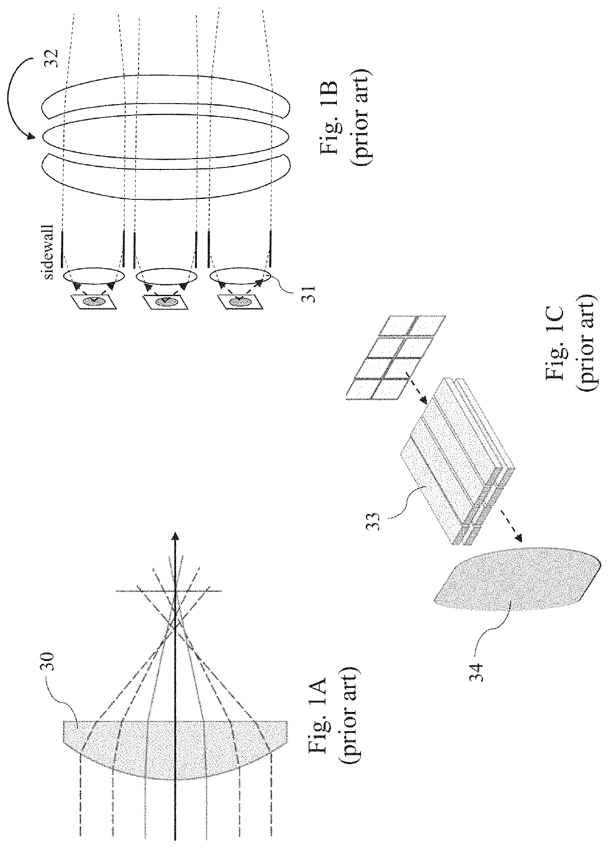
Thus, compared with the conventional lamp system, the difficulty in designing intelligent headlamps is higher. FIG. 1A is a schematic diagram illustrating an optical route of a single lens 30.
For areas having larger magnification and being closer to edges, the effect of image sharpness is more serious.
However, the conventional intelligent headlamp cannot satisfy the requirement.

Method used


Image

  • Headlight optical system and lamp using the same
  • Headlight optical system and lamp using the same
  • Headlight optical system and lamp using the same

Examples


Embodiment Construction

[0023]Reference will now be made in detail to embodiments illustrated in the accompanying drawings. Wherever possible, the same reference numbers are used in the drawings and the description to refer to the same or like parts. In the drawings, the shape and thickness may be exaggerated for clarity and convenience. This description will be directed in particular to elements forming part of, or cooperating more directly with, methods and apparatus in accordance with the present disclosure. It is to be understood that elements not specifically shown or described may take various forms well known to those skilled in the art. Many alternatives and modifications will be apparent to those skilled in the art, once informed by the present disclosure.

[0024]Unless otherwise specified, some conditional sentences or words, such as “can”, “could”, “might”, or “may”, usually attempt to express that the embodiment in the present invention has, but it can also be interpreted as a feature, element, o...


PUM

PropertyMeasurementUnit
inclined angleaaaaaaaaaa
angleaaaaaaaaaa

Abstract

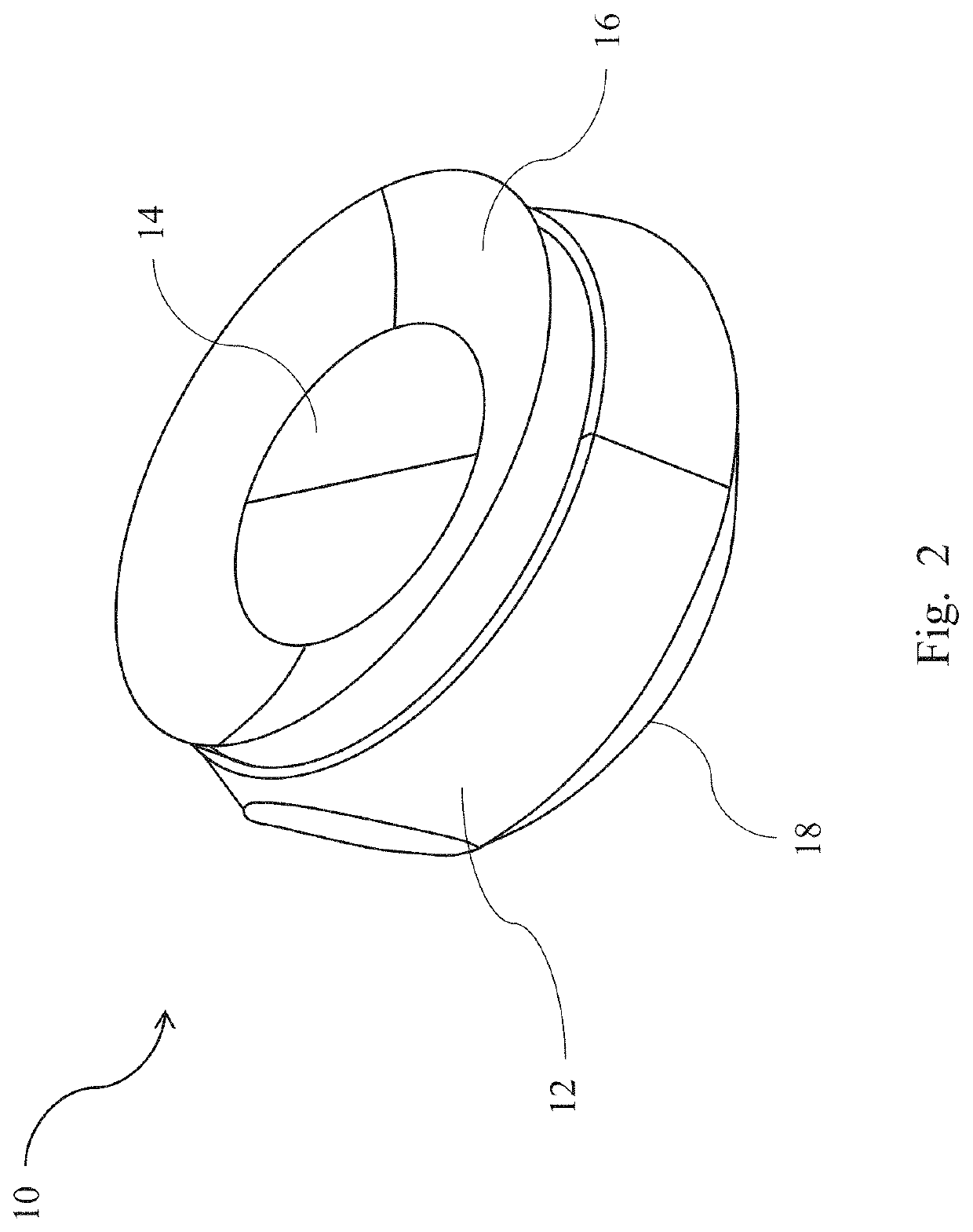
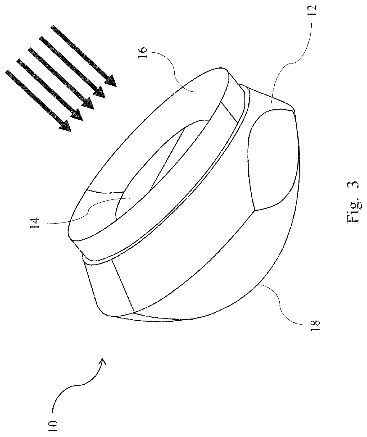
A headlight optical system and a lamp using the same are provided. The headlight optical system is implemented with the refractive optical system of a single lens. The headlight optical system includes a first incident surface, a second incident surface, and an exit surface. The first incident surface is a horizontal plane. The second incident surface surrounds the first incident surface. The inner edge of the second incident surface is connected with the outer edge of the first incident surface. The second incident surface has an inclined angle with respect to the first incident surface. After the light emitted from the polycrystalline light source is incident on the first incident surface or the second incident surface, the refractive optical system refracts and emits the light from the exit surface.

Description

BACKGROUND OF THE INVENTIONField of the Invention[0001]The present invention relates to an optical illumination system, particularly to a headlight optical system and a lamp using the same.Description of the Related Art[0002]In recent years, the development of vehicular systems focuses on safety, performance, and automatic driving assistance. Intelligent headlamps are used as one of the means of communication for advanced driver assistance systems (ADAS). In addition to electronic communication among systems, advanced driving assistance systems can also use intelligent headlamps to provide additional visual assistance, such as warnings and important reminders, as direct and fast communication between vehicles and people. For example, the conventional intelligent headlamps use the optical design with arrayed light-emitting characteristics and control the lighting of each single illumination area to implement and combine multiple small-area illumination unit modules, thereby achieving...

Claims


Application Information

Patent Timeline
Patent Type & Authority Patents(United States)
IPC IPC(8): F21V5/04F21S41/143F21S41/25F21S41/20F21Y115/10
CPCF21S41/143F21S41/25F21S41/285F21Y2115/10F21S41/153F21S41/255
Inventor SHIH, CHUN-YAOCHEN, YI-CHENG
Owner AUTOMOTIVE RES & TESTING CENT
Learn More