Passenger conveyor

a technology for passenger conveyors and conveyors, which is applied in the direction of escalators, brake types, actuators, etc., can solve the problems of unreliable, compact and simple brakes, uncontrolled rushing of people conveyors, etc., and achieve the effect of facilitating the progress of tightening

a technology for passenger conveyors and conveyors, which is applied in the direction of escalators, brake types, actuators, etc., can solve the problems of unreliable, compact and simple brakes, uncontrolled rushing of people conveyors, etc., and achieve the effect of facilitating the progress of tightening

US11034552B2Active Publication Date: 2021-06-15KONE CORP

Image

  • Passenger conveyor
  • Passenger conveyor
  • Passenger conveyor

Examples


Embodiment Construction

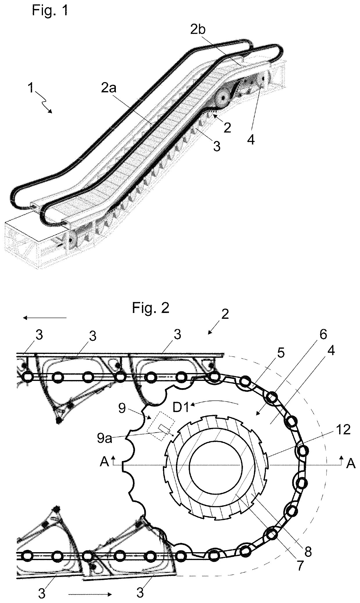
[0045]FIG. 1 illustrates a passenger conveyor 1, in particular an escalator, comprising an endless band 2 of conveying elements 3, the band 2 comprising an inclined conveying section 2a for conveying passengers standing on the conveyor elements 3 at an inclined angle upwards or downwards. The passenger conveyor 1 moreover comprises a diverting section 2b for diverting the passage of the band 2 of the conveying elements 3.

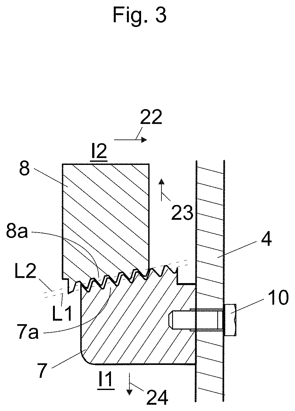
[0046]In the presented preferred embodiment, the passenger conveyor 1 is an escalator where the conveying elements are connected to each other by an endless traction member, which is in the presented case a chain 5 as presented more precisely in FIG. 2.

[0047]The passenger conveyor 1 comprises a diverting wheel 4, which is in the presented preferred embodiment a step chain sprocket wheel, for diverting the passage of the band 2 of conveying elements 3 and a traction member 5 thereof.

[0048]The passenger conveyor 1 moreover preferably comprises a motor (not illustrated...


PUM


Abstract

The invention relates to a passenger conveyor, such as an escalator or autowalk, comprising a band of conveying elements; a diverting wheel for diverting the passage of the band of conveying elements and / or a traction member thereof and a brake for braking rotation of the diverting wheel. The brake comprises a screw member having a conical threaded external rim; a nut member having a conical threaded internal rim, the screw member and nut member being screwed together, one of said screw member and nut member being connected with the diverting wheel for being driven by the diverting wheel. The brake further comprises a stopping device for stopping rotation of the other of said screw member and nut member.

Description

CROSS-REFERENCE TO RELATED APPLICATION[0001]This application is a continuation of PCT International Application No. PCT / FI2017 / 050610 which has an International filing date of Aug. 30, 2017, the entire contents of which are incorporated herein by referenceFIELD OF THE INVENTION[0002]The invention relates to stopping of movement of a passenger conveyor, such as an escalator or a moving ramp.BACKGROUND OF THE INVENTION[0003]Escalators and moving ramps are passenger conveyors, each of which typically comprises an endless band of conveying elements, such as steps or pallets for supporting the load to be transported, i.e. a person. The conveying element typically comprises guide rollers and a tread member with a tread surface on which a person can stand. The conventional passenger conveyors furthermore comprise elongated guide rails for guiding and supporting the guide rollers of the conveying elements. The conveying elements are typically connected to each other. They are typically conn...

Claims


Application Information

Patent Timeline
15 Jun 2021
Publication
US11034552B2
IPC
B66B29/00; B66B21/04; B66B21/10; F16D63/00; B66B23/02; F16D121/20; F16D125/28
CPC
B66B29/00; B66B21/04; B66B21/10; F16D63/006; B66B23/024; B66B23/026; F16D2121/20; F16D2125/28
Inventors
VIITA-AHO, TARVO; MUSTALAHTI, JORMA