Medical device

a medical device and implantable technology, applied in the field of implantable medical devices, can solve the problems of device failure, extra care, shearing or delamination, etc., and achieve the effects of improving composite structure, minimizing the risk of delamination or shearing of the device, and improving the composite structur

Active Publication Date: 2021-06-22
INVIBO COMPONENT MFG LTD
View PDF23 Cites 0 Cited by
  • Summary
  • Abstract
  • Description
  • Claims
  • Application Information

AI Technical Summary

Benefits of technology

[0004]It is an object of the present invention to provide an implantable medical device having an improved composite structure to minimize the risk of delamination or shearing of t

Problems solved by technology

However, for devices which have a varying cross section, extra care is needed to achieve the desired thickness at specific locations along the length of the device.
Typically, this is achieved by a graduated layered arrangement whereby smaller lengths of plies are placed in a stepped sequence on

Method used


Image

  • Medical device
  • Medical device
  • Medical device

Examples


Embodiment Construction

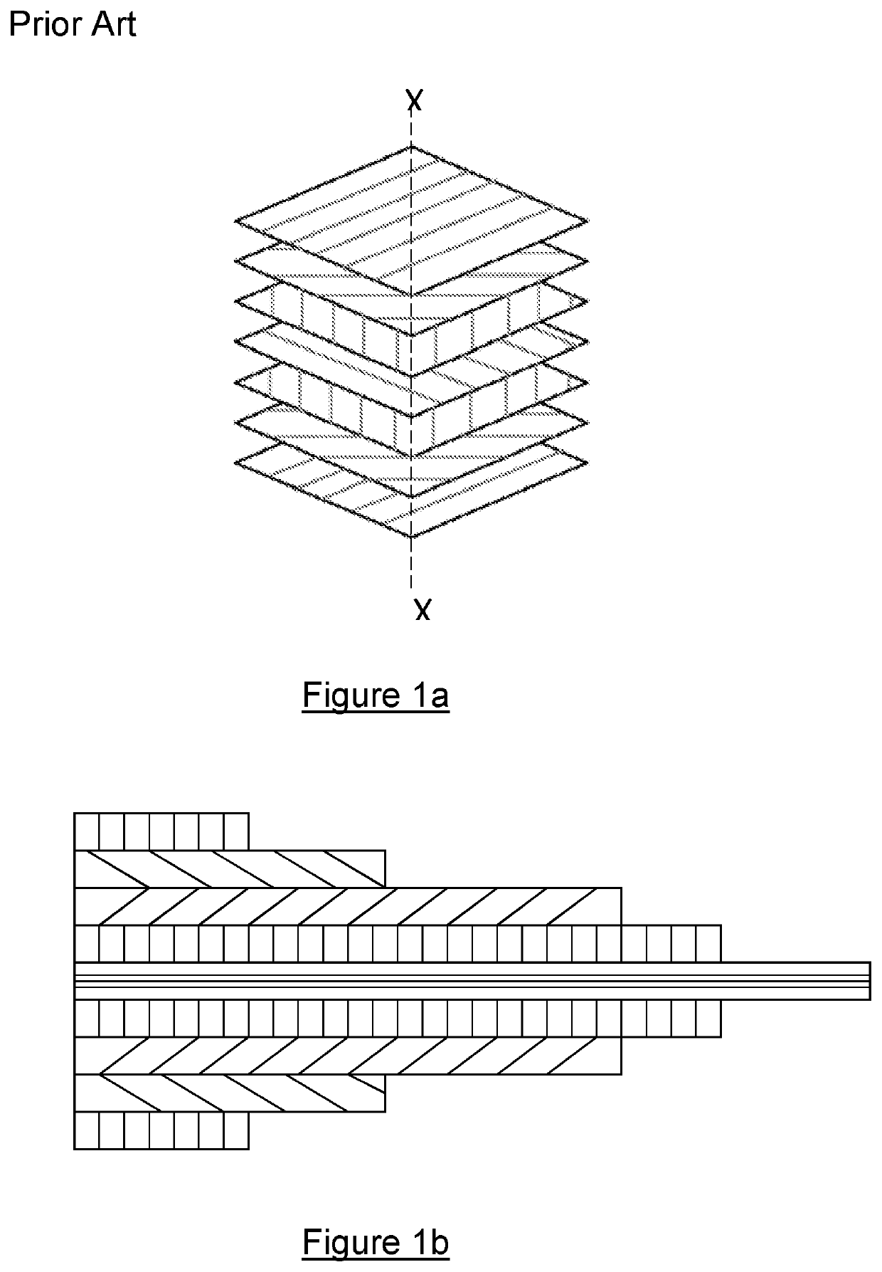
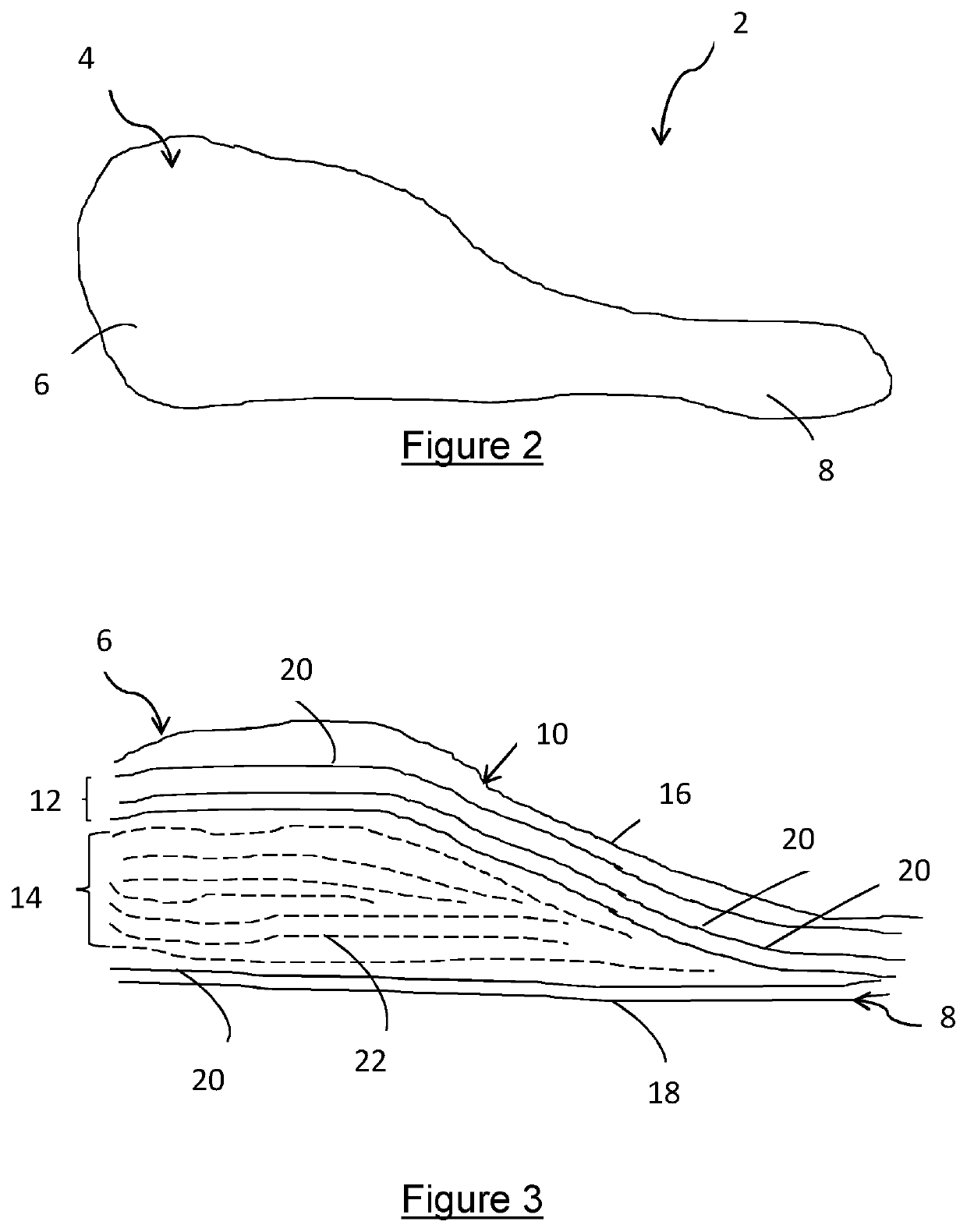
[0073]Figures 1a and 1b show typical lay-up arrangements as previously discussed. FIG. 2 shows a device 2 according to the present invention. The device 2 is an implantable medical device that comprises a body 4 having a head 6 and a tail 8. It can be seen that the cross sectional area of the device 2 varies along the longitudinal length of the body 4, with the head 6 being much greater in thickness compared to the tail 8.

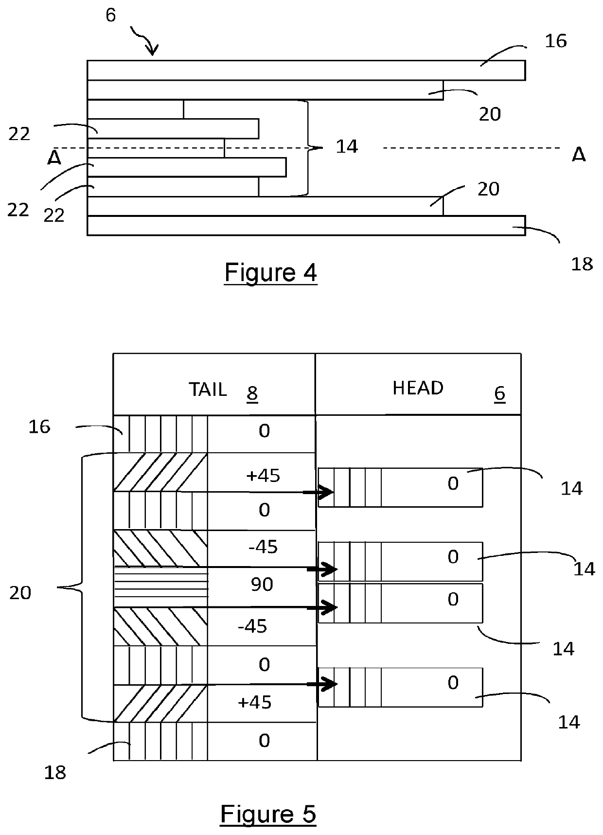
[0074]The device 2 comprises a first portion 10, a packing portion 12 and an insert 14. The first portion 10 includes a first ply 16 and a second ply 18. The first and second plies 16,18 together form the exterior surface of the device 2.

[0075]The packing portion 12 comprises a plurality of packing plies 20 which are adjacent the inner face of the first portion 10. As shown in FIG. 3, the packing plies 20 are located either side of the insert 14, and adjacent the first and second plies 16,18. The packing plies 20 are symmetrical about the longitudinal axis of the b...


PUM

PropertyMeasurementUnit
Temperatureaaaaaaaaaa
Frequencyaaaaaaaaaa
Lengthaaaaaaaaaa

Abstract

The invention relates to an implantable medical device having a body comprising a composite material. The body has a variable cross section along a length, a first portion which forms a part of a surface of said body, and a packing portion. An insert is provided in the packing portion for providing an increased thickness to at least a part of the body.

Description

TECHNICAL FIELD AND BACKGROUND[0001]The present invention relates to an implantable medical device. The invention further relates to a method of manufacturing such a device.[0002]Devices made from polymeric composite material are known. Such material has the advantage over a metal counterpart because it provides improved flexibility to the device whilst maintaining the strength required for load bearing. In addition, implantable polymeric devices are known to be less likely to cause bone deterioration in the patient.[0003]A typical polymeric composite arrangement comprises a plurality of plies of material which are compression molded together. FIG. 1a shows a common lay up configuration for an article having a constant cross section whereby unidirectional plies are orientated in a specific direction with respect to an X axis as indicated in the figure. It is known that when building such an arrangement, consideration must be given to the symmetrical nature of the stack, to minimise ...

Claims


Application Information

Patent Timeline
IPC IPC(8): A61L27/44A61F2/32A61F2/30B29C70/70A61B17/86B29C70/34A61L27/28A61B17/84B29L31/00A61B17/00A61B17/80
CPCB29C70/70A61B17/846A61B17/866A61L27/28A61L27/443A61L27/446B29C70/34A61B17/80A61B2017/00526A61B2017/00964A61L2420/04A61L2420/08B29L2031/7532B29C70/302C08L71/00
Inventor BURGESS, MICHAELLAMORLNIERE, STEVEN
Owner INVIBO COMPONENT MFG LTD
Why Eureka
Try Eureka