Laminated composite structure and related method

a composite structure and laminate technology, applied in the field can solve the problems of particularly prevalent, and affecting the quality of laminated composite structure, and achieve the effect of improving laminated composite structure and reinforcing laminated composite structur

Active Publication Date: 2015-06-18
ROLLS ROYCE PLC
View PDF3 Cites 6 Cited by
  • Summary
  • Abstract
  • Description
  • Claims
  • Application Information

AI Technical Summary

Benefits of technology

[0009]It is an object of the present disclosure to provide an improved laminated composite structure. It is another object of the present disclosure to provide an improved method for reinforcing a laminated composite structure.

Problems solved by technology

This problem has been found to be particularly prevalent in composite laminates in which adjacent laminae have constituent fibres which are not aligned.
As the ultrasonic hammer urges the pins into the composite structure, it induces high frequency vibrations in them.
However, there are significant disadvantages in using this type of material for the pins.
For example fibrous composite pins have a tendency to split during aggressive penetration of the structure to be reinforced, the material of the pins is rather brittle and can result in premature failure of the pins, and the pins will have a low transverse modulus and strength which reduces their effectiveness in shear loading of the reinforced structure.
However, metal pins have heretofore suffered from a significant disadvantage themselves arising from the fact that their coefficient of thermal expansion is poorly matched to that of the composite materials which there are intended to reinforce.
This can result in early debonding of the pins from the surrounding matrix material of the composite during the manufacturing process, thereby degrading the pins' reinforcing performance.

Method used


Image

  • Laminated composite structure and related method
  • Laminated composite structure and related method
  • Laminated composite structure and related method

Examples


Embodiment Construction

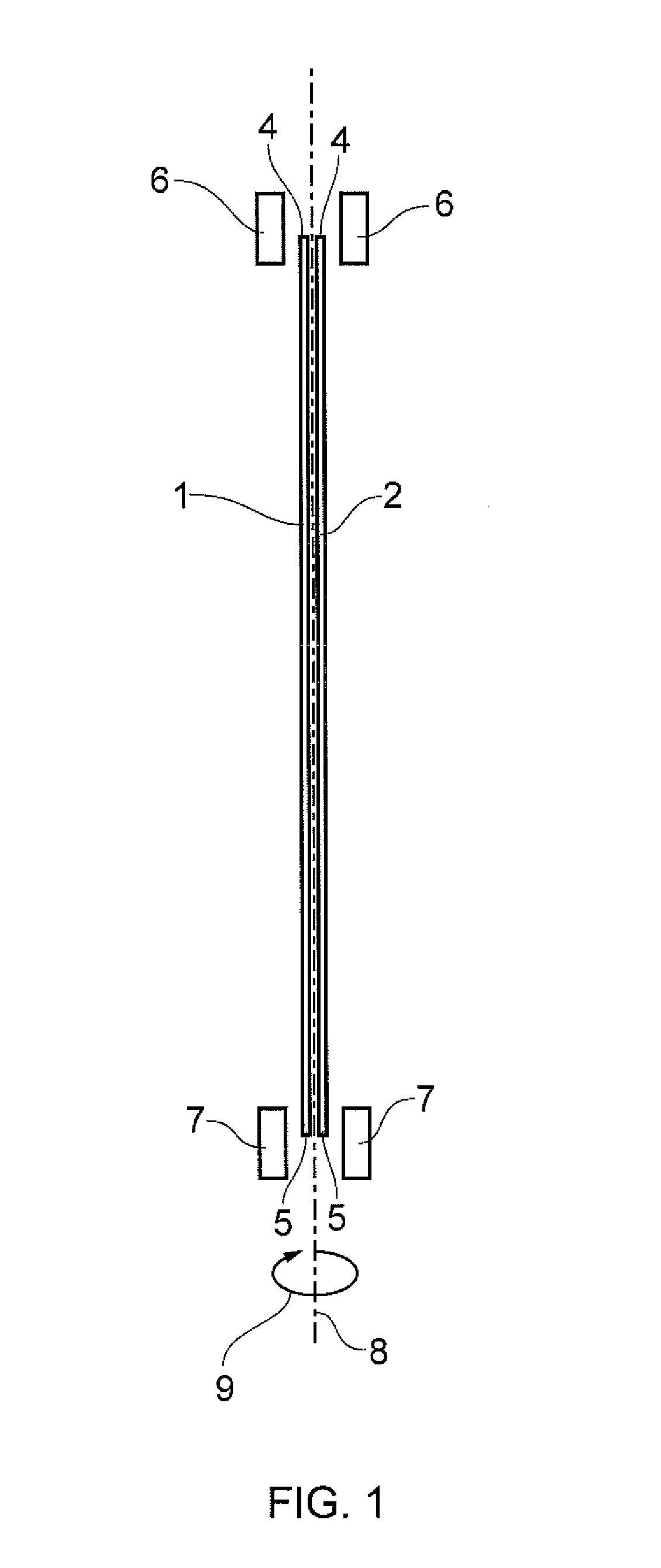
[0032]Turning now to consider FIG. 1 in more detail, there is shown a pair of substantially identical elongate metal filaments 1, 2 which are used to form a reinforcing pin for z-pinning reinforcement of laminated composite structures, as will be explained in more detail below. The filaments 1, 2 may be provided in the form of lengths of plastically deformable wire. Whilst it is envisaged that in most embodiments of the present disclosure the filaments will have a generally circular transverse cross-section, it is possible for the filaments to have alternative cross-sectional shapes and they may be, for example, polygonal in cross section.

[0033]The filaments may be formed from a ductile material having high tensile and transverse strength properties, such as steel or a nickel-titanium alloy.

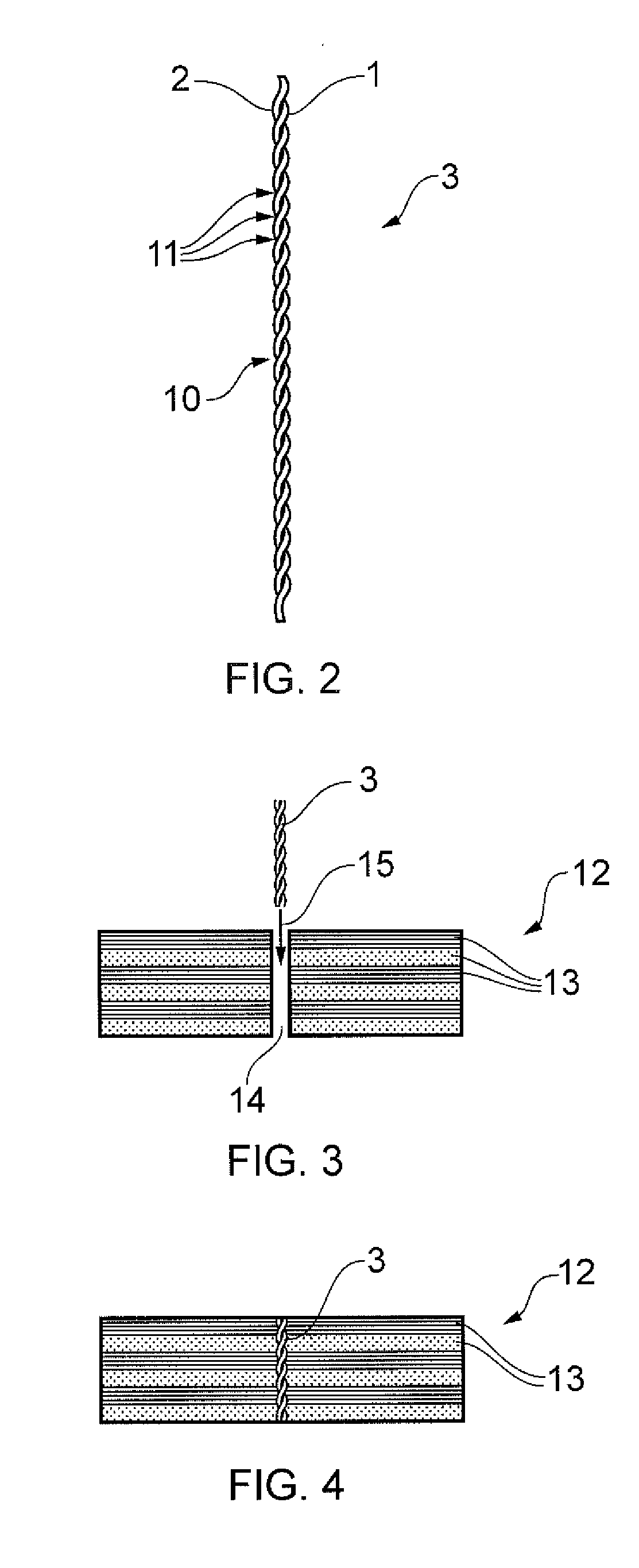
[0034]Each filament 1, 2 has a cross-sectional thickness which is slightly less than half of the desired diameter of the reinforcing pin 3 (shown in FIG. 2) to be produced from the filaments. So ...


PUM

PropertyMeasurementUnit
diameteraaaaaaaaaa
thicknessaaaaaaaaaa
lengthaaaaaaaaaa

Abstract

There is disclosed a laminated composite structure (12) having a plurality of laminae (13) formed of composite material, and at least one reinforcing pin (3) provided within the structure so as to extend between adjacent laminae (13). The or each said reinforcing pin (3) is formed from a plurality of interlaced metal filaments (1, 2). There is also disclosed a related method for reinforcing a laminated composite structure (12) via the use of at least one said reinforcing pin (3).

Description

CROSS-REFERENCE TO RELATED APPLICATIONS[0001]This application is based upon and claims the benefit of priority from British Patent Application Number 1322274.0 filed 17 Dec. 2013, the entire contents of which are incorporated by reference.BACKGROUND[0002]1. Field of the Disclosure[0003]The present disclosure relates to laminated composite structure, and more particularly relates a composite laminated structure having at least one reinforcing pin. The disclosure also relates to a method for reinforcing a laminated composite structure.[0004]2. Description of the Related Art[0005]It is well known in the field of composite structures that two-dimensional composite laminates are relatively weak in the so-called “through thickness” or z-direction. At the interfaces between adjacent laminae in such structures there is a high tendency for the plies to debond or delaminate. This problem has been found to be particularly prevalent in composite laminates in which adjacent laminae have constitu...

Claims


Application Information

Patent Timeline
Patent Type & Authority Applications(United States)
IPC IPC(8): B32B3/06B32B7/08
CPCB32B3/06B32B5/00B32B5/02B32B5/06B32B5/10B32B5/22B32B5/24B32B5/26B32B5/28B32B7/00B32B7/04B32B7/08B32B19/02B32B19/04B32B27/00B32B27/02B32B27/04B32B27/06B32B27/12B32B27/28B32B3/00B32B3/26B32B3/266B29C70/24Y10T428/12333Y10T428/192Y10T29/49826
Inventor YASAEE, MEHDI
Owner ROLLS ROYCE PLC
Why Eureka
Try Eureka