Optimized regenerative braking control of electric motors using look-up tables

a technology of look-up tables and electric motors, applied in the direction of dynamo-electric converter control, dynamo-electric gear control, stopping arrangements, etc., can solve the problems of nonlinearity of the operative set of differential equations and complicated field-oriented control of ac motors, and achieve the effect of maximizing the charging curren

Active Publication Date: 2021-06-22
TEXAS INSTR INC
View PDF8 Cites 0 Cited by
  • Summary
  • Abstract
  • Description
  • Claims
  • Application Information

AI Technical Summary

Benefits of technology

[0012]Disclosed embodiments provide such a system and method that is compatible with external braking mechanisms.
[0014]According to certain embodiments, a FOC system and method is provided in which multiphase control signals to be applied to the motor during braking are determined so as to perform regenerative braking when possible, and in some embodiments to optimize the energy recovery from regenerative braking. In these embodiments, a lookup table storing data representative of regenerative braking regions in the torque-speed plane is accessed in the determination of the multiphase control signals. In some embodiments, the lookup table stores data representative of operating points of maximum regenerative braking current.

Problems solved by technology

Field-oriented control of AC motors is a complicated task because the rotation of the magnetic field in the stator with respect to the rotating magnetic field of the rotor can be asynchronous, such that characterization of the operation of the AC motor involves a set of differential equations with time varying coefficients.
Indeed, the operative set of differential equations is still nonlinear even in those systems in which the magnetic fields of the stator and rotor are synchronous.

Method used


Image

  • Optimized regenerative braking control of electric motors using look-up tables
  • Optimized regenerative braking control of electric motors using look-up tables
  • Optimized regenerative braking control of electric motors using look-up tables

Examples


Embodiment Construction

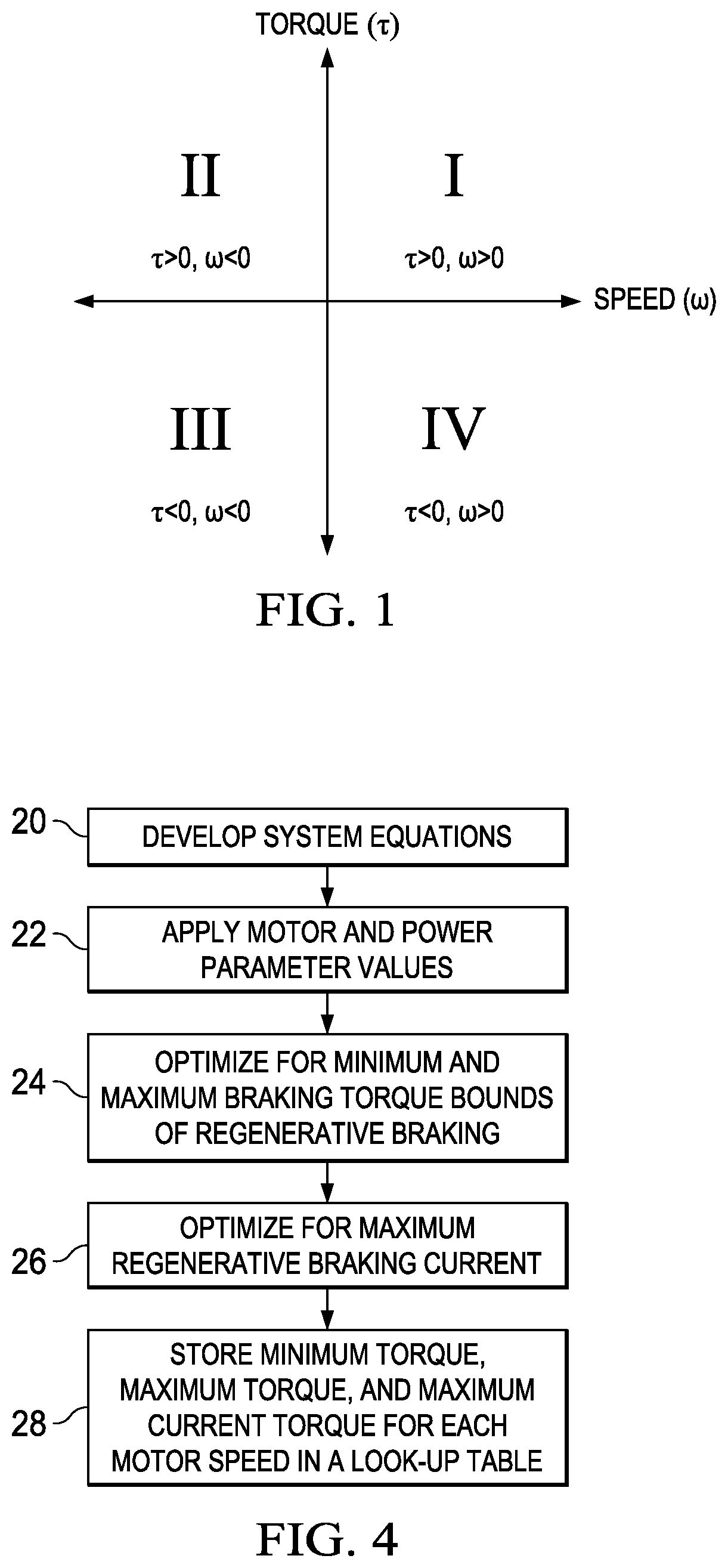
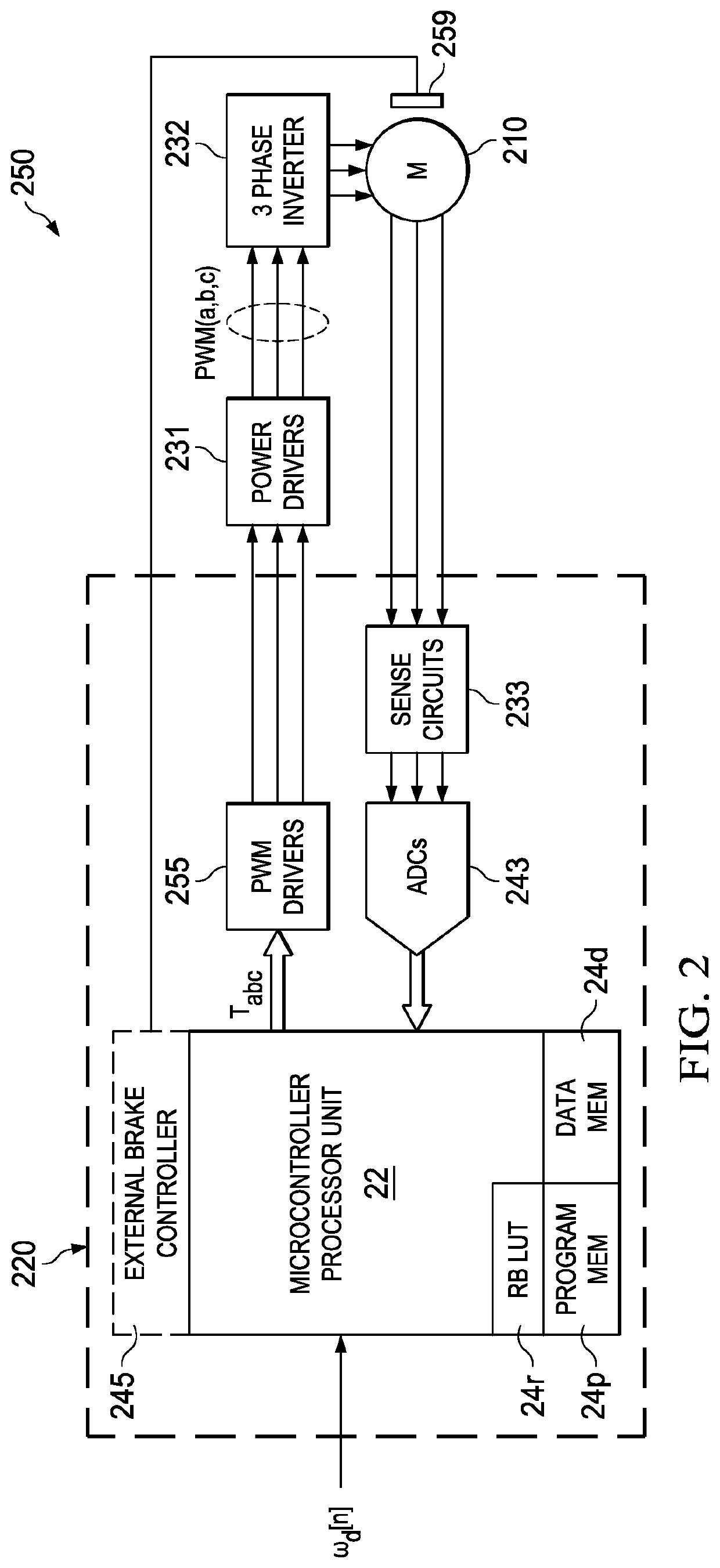
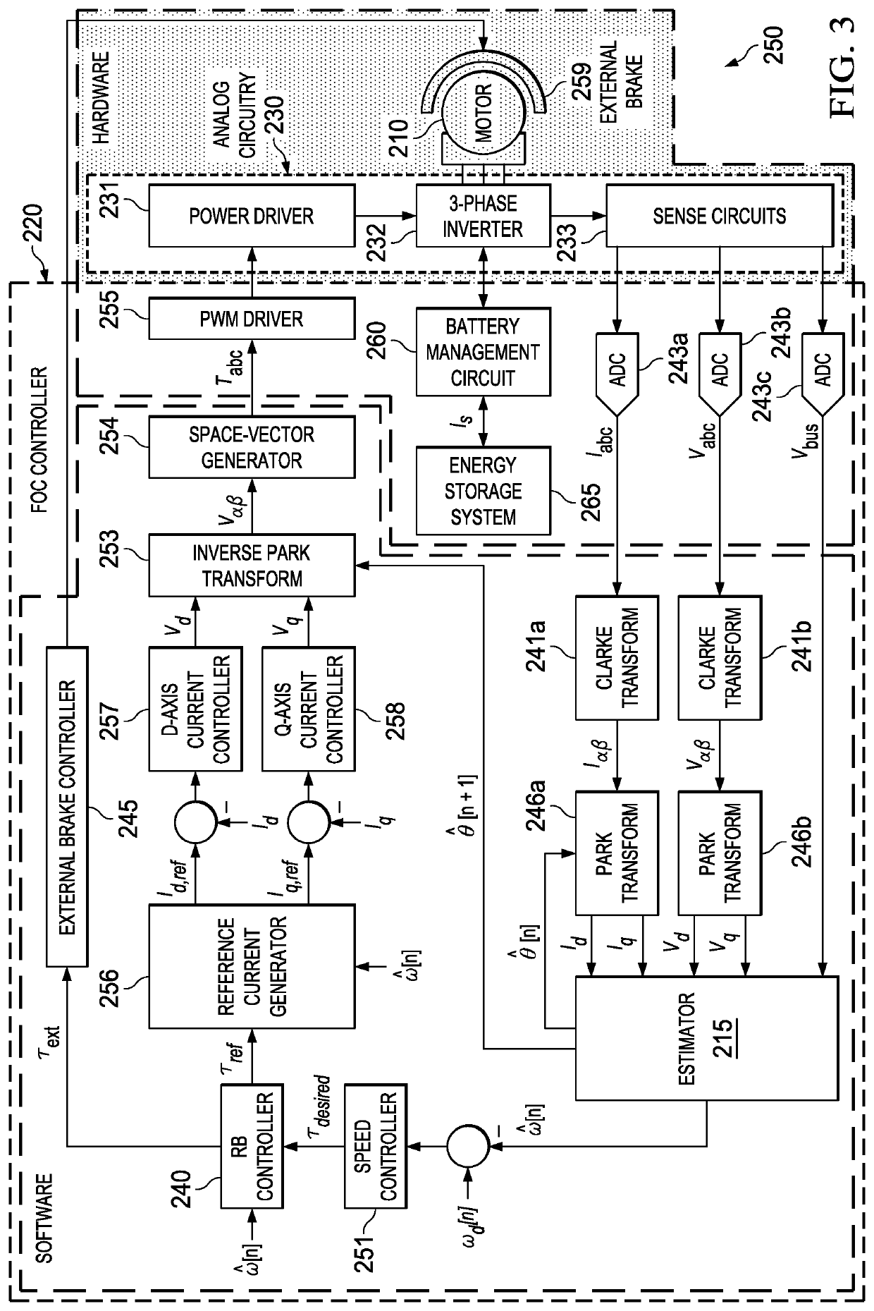
[0023]The one or more embodiments described in this specification are implemented into a field-oriented control (FOC) scheme for a permanent magnet (PM) type of an AC electric motor, as it is contemplated that such implementation is particularly advantageous in that context. However, it is also contemplated that concepts of this invention may be beneficially applied to other applications, for example other types of electric motors such as AC induction motors, and other machines. Accordingly, it is to be understood that the following description is provided by way of example only, and is not intended to limit the true scope of this invention as claimed.

[0024]FIG. 2 illustrates, in the form of a block diagram, an example of a field-oriented control (FOC) control system 250 for an electric machine, according to an embodiment. In the example of FIG. 2, the electric machine under control of this system is permanent magnet synchronous motor 210, which has three stator windings arranged 12...


PUM


Abstract

A regenerative braking controller for an AC motor. To determine an electromagnetic torque for slowing or stopping the motor, the regenerative braking controller accesses a lookup table to retrieve an braking torque value corresponding to a current estimate of rotor velocity. The retrieved braking torque may correspond to a maximum or minimum torque level at which regenerative braking will occur at the current rotor velocity, or to a torque level at which charging current during regenerative braking will be maximized. If an external mechanical brake is present, the regenerative braking controller can forward an external braking torque signal to a controller so that the mechanical brake can apply the remainder of the braking force beyond that indicated by the regenerative braking torque. A method for establishing the braking torques to be stored in the lookup table is also disclosed.

Description

CROSS-REFERENCE TO RELATED APPLICATIONS[0001]Not applicable.STATEMENT REGARDING FEDERALLY SPONSORED RESEARCH OR DEVELOPMENT[0002]Not applicable.BACKGROUND OF THE INVENTION[0003]This invention is in the field of control systems for electric machines. Embodiments described in this specification are more specifically directed to control of electric motors to recover energy using regenerative braking.[0004]Field-oriented control (“FOC”) has become commonplace in modern control systems for AC electric motors. According to this approach, stator windings of the AC motor are driven, for example by pulse-width-modulation, in such a way as to maximize the torque / ampere performance of the motor. Field-oriented control of AC motors is a complicated task because the rotation of the magnetic field in the stator with respect to the rotating magnetic field of the rotor can be asynchronous, such that characterization of the operation of the AC motor involves a set of differential equations with time...

Claims


Application Information

Patent Timeline
Patent Type & Authority Patents(United States)
IPC IPC(8): B60L7/14H02P3/16B60L15/20B60L15/02B60L7/18H02P21/22H02P21/36H02P27/08
CPCB60L7/14B60L7/18B60L15/025B60L15/2009H02P3/16H02P21/22H02P21/36H02P27/08B60L2240/421B60L2240/423B60L2240/427B60L2240/429Y02T10/64Y02T10/72H02P6/24
Inventor MURTHY, ARAVIND SAMBAMAGEE, DAVID PATRICK
Owner TEXAS INSTR INC
Why Eureka
Try Eureka