Vehicle

a technology for vehicles and braking systems, applied in the field of vehicles, can solve the problems of limited amount of energy recovered by regenerative braking systems, and achieve the effects of maximizing use, supplementing regenerative braking, and optimising energy recovery

Active Publication Date: 2016-08-25
BENTLEY MOTORS
View PDF9 Cites 3 Cited by
  • Summary
  • Abstract
  • Description
  • Claims
  • Application Information

AI Technical Summary

Benefits of technology

[0007]Providing automatic control of the braking systems helps to avoid a driver's driving style from impairing the ability of the braking system to recover energy. As the system decelerates the vehicle so that its speed corresponds to that of the obstacle, the system is useful for both slowing a vehicle to a stop and for slowing a vehicle to the speed of a slower moving vehicle in front.
[0008]To optimise energy recovery the brake controller may be operative to maximise use of the regenerative braking system, as compared to the friction braking system, when decelerating the vehicle.
[0009]The brake controller may deploy the braking systems in order to achieve a substantially linear deceleration of the vehicle. This approach tends to reduce the need to supplement regenerative braking with friction braking.

Problems solved by technology

In practice the amount of energy that is recovered by regenerative braking systems is limited by a driver's driving style, Heavy braking usually requires both regenerative and friction brakes to operate.

Method used


Image

  • Vehicle
  • Vehicle
  • Vehicle

Examples


Embodiment Construction

[0017]In order that the invention may be more clearly understood an embodiment thereof will now be described, by way of example only, with reference to the accompanying drawings, of which:

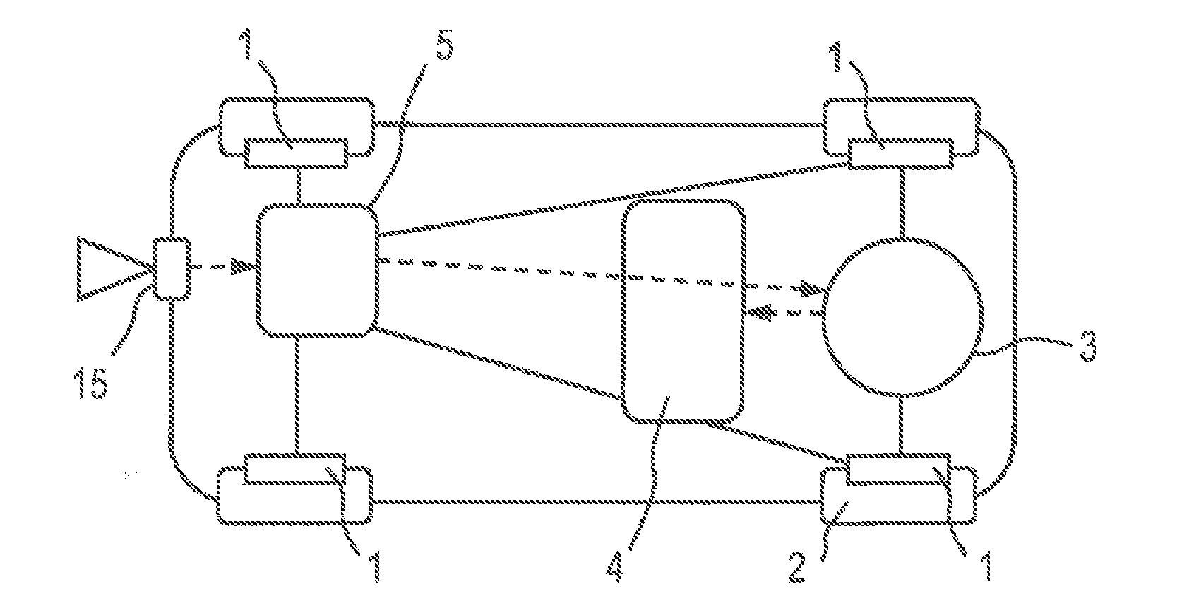
[0018]FIG. 1 is a schematic diagram of an automobile fitted with regenerative and friction braking systems and a brake control system;

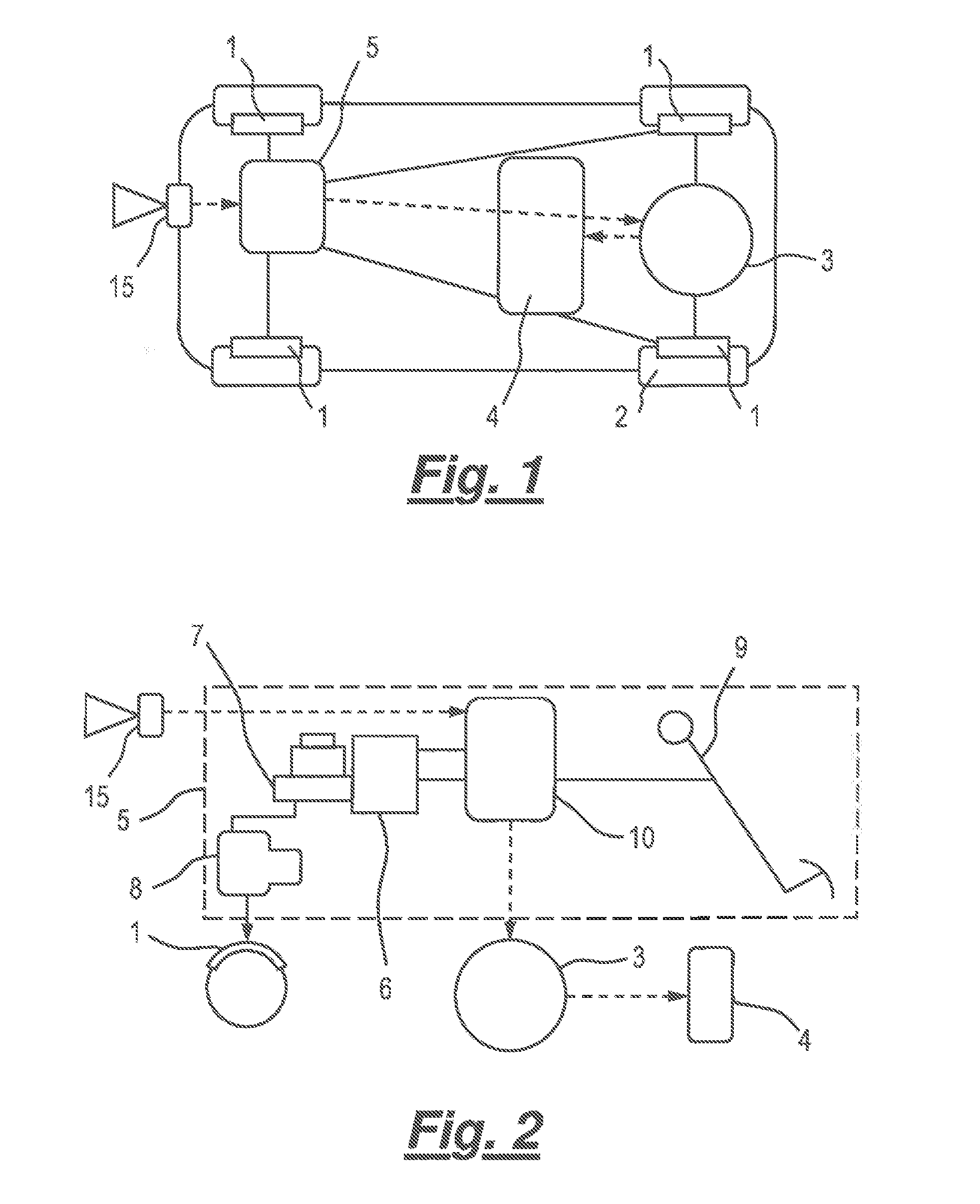
[0019]FIG. 2 is a schematic diagram showing further detail of the brake control system of FIG. 1;

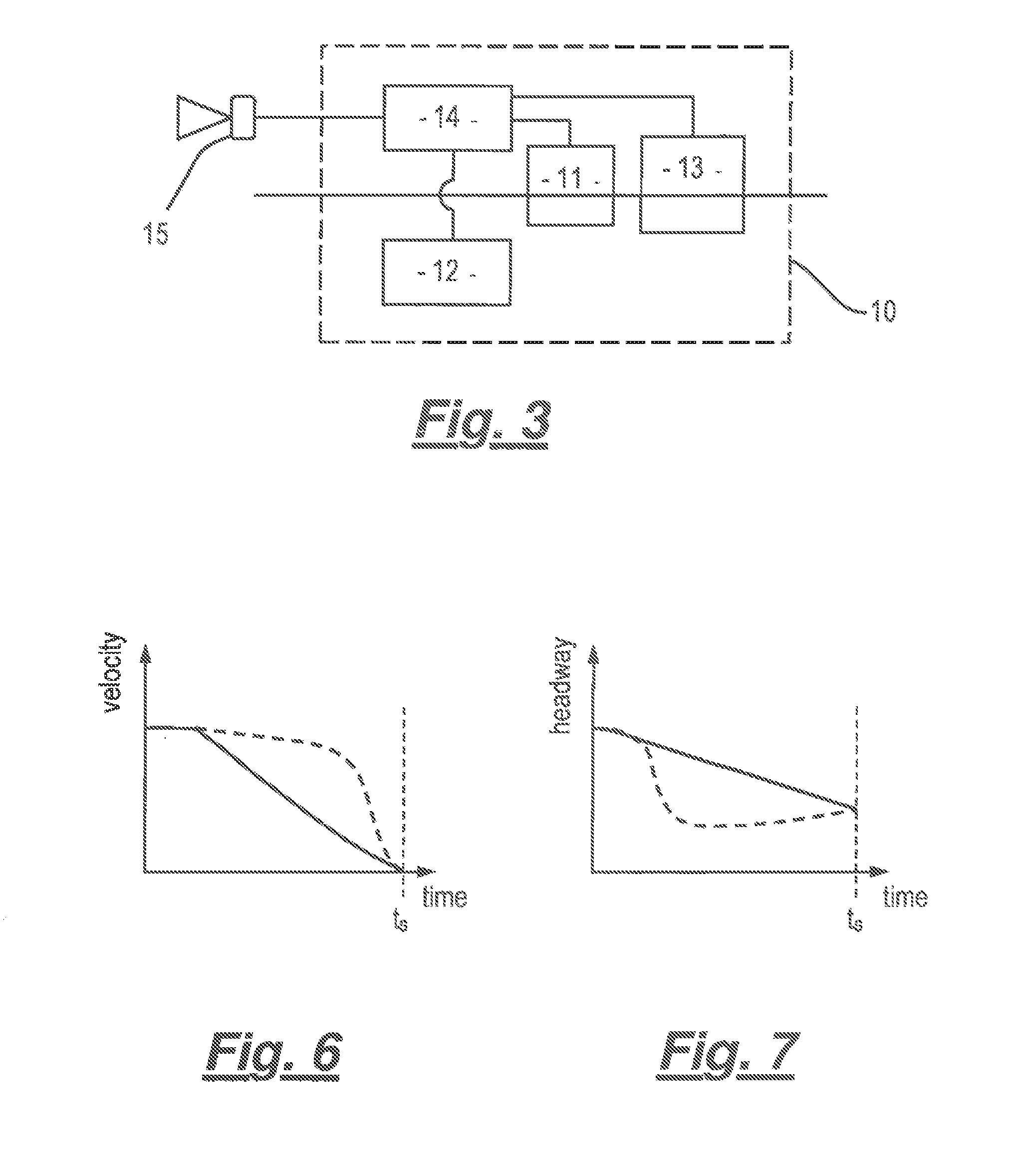
[0020]FIG. 3 is a schematic diagram showing further detail of the brake controller;

[0021]FIG. 4 is a flow chart showing an automatic brake operating mode;

[0022]FIG. 5 is a flow chart showing how a driver selects the automatic mode;

[0023]FIG. 6 is a graph showing automobile velocity against time; and

[0024]FIG. 7 is a graph showing automobile headway against time.

[0025]Referring to the drawing, and initially figure an automobile is provided with a friction braking system. This comprises conventional hydraulically actuated disc brakes 1, one for each of the four road wheels ...


PUM


Abstract

A vehicle, such as an automobile, is provided with friction 1 and regenerative 3,4,5 braking systems. A sensor 15 detects an obstacle in the vehicle's path and a brake controller 5, when operated by a user, automatically deploys either or both braking systems to decelerate the vehicle so that its speed corresponds to that of the obstacle when the vehicle is a predetermined distance from the obstacle. The brake controller is arranged to deploy the braking systems in order to optimise recovery of kinetic energy by the regenerative braking system. The brake controller may be operated in a standard mode, in which it deploys the braking systems to provide a retarding force on the vehicle which depends on a driver's input. The brake controller may he controlled by a brake pedal 9. The pedal may have a position part way along its travel at which resistance to further travel temporarily increases and operation of the pedal beyond that position causes the brake controller to operate in the standard mode.

Description

TECHNICAL FIELD OF THE INVENTION[0001]The present invention relates to a vehicle, particularly, but not exclusively, an automobile, with friction and regenerative braking systems.BACKGROUND TO THE INVENTION[0002]Automobiles with an electric propulsion system, such as those with hybrid drive system comprising an internal combustion engine, an electric traction motor and an electric battery, as well an pure electric vehicles, typically deploy regenerative braking in order to recover and store the vehicle's kinetic energy for use in propelling the vehicle. This is achieved by using an electric traction motor in reverse, as a generator, to convert rotational kinetic energy from the vehicle's road wheels to electrical energy which is stored in an electrical battery on the vehicle.[0003]Owing to the capacity of typical electrical traction motors and other characteristics of electrical traction systems the regenerative braking systems cannot absorb energy as rapidly as it can be dissipated...

Claims


Application Information

Patent Timeline
Patent Type & Authority Applications(United States)
IPC IPC(8): B60L15/10B60W30/09B60L7/26B60L15/20B60T7/22B60L3/00
CPCB60T2201/022B60T7/22B60W10/184B60W30/09B60W2050/009B60Y2300/89B60T1/10B60L3/0015B60L3/12B60L7/10B60L15/10B60L15/2009B60W10/08B60W30/18127Y02T10/6265Y02T10/7258B60Y2200/91B60W10/188B60K6/22B60Y2200/92Y10S903/947B60L7/26B60K6/52B60L2240/12B60L2240/80B60L2250/26Y02T10/72B60W20/00B60W2510/083B60W2510/18B60W2510/244B60W2540/12B60W20/10Y02T10/62Y02T10/64B60W30/14
Inventor O'MEACHAIR, DEAGIAN
Owner BENTLEY MOTORS
Why Eureka
Try Eureka