Supercharge Your Innovation With Domain-Expert AI Agents!

Parametric array system

a parametric array and array technology, applied in the field of parametric array systems, can solve the problems of difficult to transmit a sound by the conventional parametric array system, and achieve the effect of reducing the sound pressure level of an audible sound

Active Publication Date: 2021-06-22
MITSUBISHI ELECTRIC ENG CO LTD
View PDF4 Cites 0 Cited by
  • Summary
  • Abstract
  • Description
  • Claims
  • Application Information

AI Technical Summary

Benefits of technology

[0013]According to the present invention, because it is configured as above, it is possible to emit both the carrier wave signal and the modulated wave signal in the same direction, and reduce the sound pressure level of an audible sound at a distant place at a certain distance or more in the emitting direction.

Problems solved by technology

Therefore, it is difficult for the conventional parametric array system to transmit a sound only to a certain specific area.

Method used


Image

  • Parametric array system
  • Parametric array system
  • Parametric array system

Examples


embodiment 1

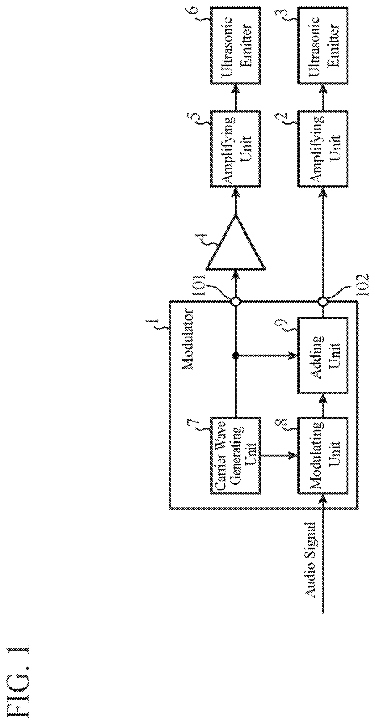
[0022]FIG. 1 is a block diagram showing an example of the schematic configuration of a parametric array system according to Embodiment 1 of the present invention.

[0023]The parametric array system includes a modulator 1, an amplifying unit 2, an ultrasonic emitter (first ultrasonic emitter) 3, a gain adjusting unit 4, an amplifying unit 5 and an ultrasonic emitter (second ultrasonic emitter) 6, as shown in FIG. 1. Further, the modulator 1 includes a carrier wave generating unit 7, a modulating unit 8 and an adding unit 9.

[0024]The carrier wave generating unit 7 generates a carrier wave signal in an ultrasonic band. The carrier wave signal generated by the carrier wave generating unit 7 is outputted to the modulating unit 8 and the adding unit 9, and is also outputted to the gain adjusting unit 4 via an outputting unit 101 of the modulator 1.

[0025]The modulating unit 8 generates a modulated wave signal by performing amplitude modulation on the carrier wave signal generated by the carr...

embodiment 2

[0058]In Embodiment 1, the example of adding a carrier wave signal and a modulated wave signal which are electric signals by using the adding unit 9 is shown. In contrast with this, in Embodiment 2, an example in which an ultrasonic emitter 11 emits a carrier wave signal and a modulated wave signal, with these wave signals being separated from each other, and the wave signals are combined in the air will be shown.

[0059]FIG. 6 is a block diagram showing an example of the schematic configuration of a parametric array system according to Embodiment 2 of the present invention. In the parametric array system according to Embodiment 2 shown in this FIG. 6, in contrast to the parametric array system according to Embodiment 1 shown in FIG. 1, the adding unit 9 is removed, an amplifying unit 10 is added, and the ultrasonic emitter 3 is changed to the ultrasonic emitter 11. The other components are the same as those shown in FIG. 1, and are denoted by the same reference numerals and the expla...


PUM


Abstract

A carrier wave generating unit for generating a carrier wave signal; a modulating unit for generating a modulated wave signal by performing amplitude modulation on the carrier wave signal generated by the carrier wave generating unit with an audio signal; an adding unit for adding the carrier wave signal generated by the carrier wave generating unit and the modulated wave signal generated by the modulating unit to generate a signal; an ultrasonic emitter for emitting the signal generated by the adding unit, and an ultrasonic emitter arranged on the central axis of the ultrasonic emitter and ahead of the emitting surface of the ultrasonic emitter, for emitting the carrier wave signal generated by the carrier wave generating unit in the same direction as the emitting direction of the ultrasonic emitter are included, wherein the phase of the carrier wave signal emitted by the ultrasonic emitter is opposite to that of the carrier wave signal included in the signal emitted by the ultrasonic emitter.

Description

TECHNICAL FIELD[0001]The present invention relates to a parametric array system that emits an audible sound to a narrow area by using a carrier wave signal in an ultrasonic band.BACKGROUND ART[0002]A parametric array system adds a modulated wave signal which is generated by performing amplitude modulation on a carrier wave signal in an ultrasonic band with an audio signal being an audible sound, and the carrier wave signal, and emits the added signals from an ultrasonic emitter. As a result, in the air, a difference tone between the carrier wave signal and the modulated wave signal occurs due to a nonlinear interaction between the carrier wave signal and the modulated wave signal, and the audible sound is self-demodulated.[0003]This parametric array system has propagation characteristics having, for example, sound pressure levels as shown in FIG. 7. In FIG. 7, the horizontal axis shows the distance from the ultrasonic emitter, and the vertical axis shows the sound pressure level. Fu...

Claims


Application Information

Patent Timeline
Patent Type & Authority Patents(United States)
IPC IPC(8): H04B11/00H04R3/12H01Q21/00
CPCH04B11/00H01Q21/0006H04R3/12H04R2217/03
Inventor YOSHIDA, SHUNJI
Owner MITSUBISHI ELECTRIC ENG CO LTD
Features
  • R&D
  • Intellectual Property
  • Life Sciences
  • Materials
  • Tech Scout
  • Unparalleled Data Quality
  • Higher Quality Content
  • 60% Fewer Hallucinations
Learn More