Integrated operator centric controls

a technology of operator centric control and control interface, applied in non-electric variable control, process and machine control, instruments, etc., can solve the problems of duplicate control interface, inelegant control interface, etc., and achieve the effect of facilitating transit operations

Active Publication Date: 2021-07-13
OSHKOSH CORPORATION
View PDF48 Cites 20 Cited by
  • Summary
  • Abstract
  • Description
  • Claims
  • Application Information

AI Technical Summary

Benefits of technology

This patent describes a vehicle that has a rolling chassis and a working component. The control interface is on the chassis and can control the non-moving part of the vehicle. The working component moves and is controlled by the control interface. This allows for seamless movement and control of the vehicle. The control system includes a control interface and a control interface module that can control both the non-moving and moving parts of the vehicle. This invention has technical benefits in improving the efficiency and control of vehicles.

Problems solved by technology

This produces duplicative, and in some instances inelegant, controls interfaces.

Method used


Image

  • Integrated operator centric controls
  • Integrated operator centric controls
  • Integrated operator centric controls

Examples


Embodiment Construction

[0016]Before turning to the figures, which illustrate the exemplary embodiments in detail, it should be understood that the present application is not limited to the details or methodology set forth in the description or illustrated in the figures. It should also be understood that the terminology is for the purpose of description only and should not be regarded as limiting.

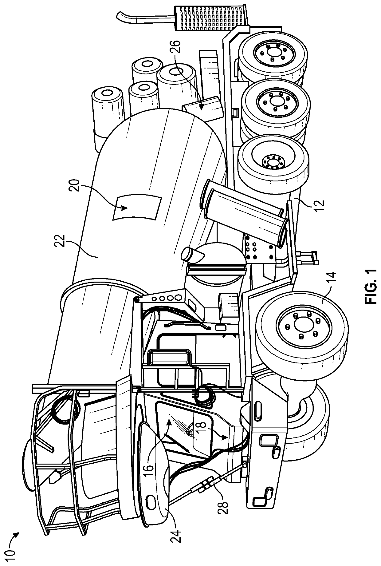
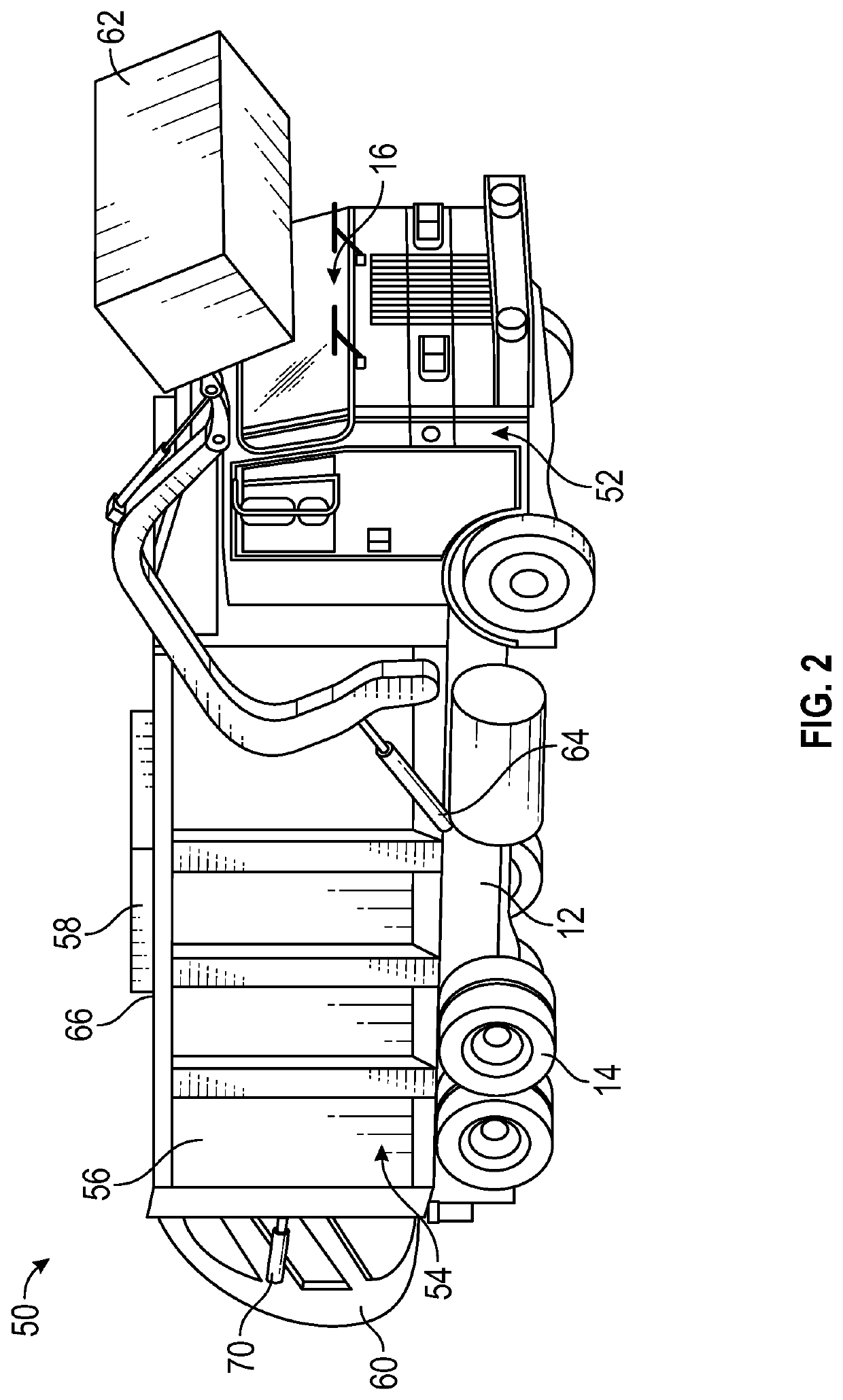
[0017]A vehicle may include both working and non-working components. As referred to herein, the term “non-working components” generally refers to components that are included in the vehicle as part of a rolling chassis structure (e.g., configuration) sold by an original equipment manufacturer (OEM). The non-working components may be configured to facilitate transit operations (e.g., vehicle movement, steering, operator entertainment, etc.). For example, the non-working components may include electrical components in a cab area of the vehicle such as dashboard displays, radios, etc. The non-working components may ...


PUM

PropertyMeasurementUnit
areaaaaaaaaaaa
rotationaaaaaaaaaa
productivityaaaaaaaaaa

Abstract

A vehicle includes a rolling chassis structure and a working component coupled to the rolling chassis structure. The rolling chassis structure includes a chassis, a non-working component, and a control interface. The non-working component is coupled to the chassis and is configured to facilitate transit operations for the rolling chassis structure. The control interface is disposed in a cab area of the chassis. The control interface is communicably coupled to the non-working component and is configured to control operation of the non-working component. The working component is configured to move relative to the chassis and is communicably coupled to the control interface. The control interface is configured to control movement of the working component.

Description

CROSS-REFERENCE TO RELATED PATENT APPLICATIONS[0001]The present application is a continuation of U.S. patent application Ser. No. 16 / 789,172, filed Feb. 12, 2020, which claims the benefit of and priority to U.S. Provisional Patent Application No. 62 / 805,797, filed Feb. 14, 2019, the contents of which are hereby incorporated by reference in their entirety.BACKGROUND[0002]Refuse trucks (e.g., garbage trucks) and concrete mixers are sometimes manufactured by adding components to rolling chassis configurations sold by original equipment manufacturers (OEMs). For example, a refuse truck may be manufactured by adding a refuse cab, a refuse body (e.g. refuse collection body), and other refuse-specific components to an OEM vehicle chassis. A concrete mixer may be manufactured by adding a mixer cab, a mixer body (e.g., a mixing drum), and other mixer-specific components to an OEM vehicle chassis. The rolling chassis configuration may include an engine, drivetrain, and associated user control...

Claims


Application Information

Patent Timeline
Patent Type & Authority Patents(United States)
IPC IPC(8): B60R16/023B60K35/00B65F3/14B28C5/42G05D17/02B65F3/04B60K37/06B65F3/02
CPCB60R16/0231B28C5/422B60K35/00B65F3/041B65F3/14G05D17/02B60K37/06B65F2003/0283B60Y2200/41B28C5/4206B60P3/16B65F3/02B65F2003/0279B60K35/10B60K35/60B60K2360/782B60K2360/148B60K2360/1446
Inventor WILDGRUBE, GRANTROCHOLL, JOSHUA D.CLIFTON, CODY D.KELLANDER, JOHN T.
Owner OSHKOSH CORPORATION
Why Eureka
Try Eureka