Wheel sensors within vehicular brake assemblies

a technology of brake assemblies and sensors, applied in the field of wheel speed sensors, can solve the problems of less cost of including performance sensors, less cost of total system cost, and increased cost of vehicle manufacturers, purchasers, and users, and achieves the effects of improving the orientation and configuration system of sensing, being inexpensive to manufacture and maintain, and increasing traffic safety during vehicle operation

Active Publication Date: 2021-07-20
DEXTER AXLE CO LLC
View PDF23 Cites 0 Cited by
  • Summary
  • Abstract
  • Description
  • Claims
  • Application Information

AI Technical Summary

Benefits of technology

[0005]Accordingly, a primary objective of the present invention is to provide an improved sensing orientation and configuration system for brake assemblies. These improvements include providing apparatus for detecting wheel speed and / or other operating characteristics which are inexpensive to manufacture and maintain, increase traffic safety during vehicle operation, minimize component weight, facilitate use and repair, and are durable and reliable over extended use and with a wider variety of vehicles. Further, tolerance of endplay of rotating components without losing the ability to detect wheel speed is an objective.SUMMARY OF THE INVENTION
[0006]These and other objectives of the present invention are achieved by the provision of detectable indicia on the interior diameter surface or circumferential rim of the brake hub-drum adjacent to, and spaced apart from, the backing plate or another structural member of the brake. A sensor is fixed with respect to the backing plate to detect wheel speed and / or other operating conditions detectable from the motion and / or relative location or condition of those indicia. The number of indicia used and the indicia spacing along the interior circumferential rim is selected as needed for a given type of sensor and / or a given application. In the case of a speed sensor, the indicia can be a series of notches in the rim along the entire interior circumferential rim, resembling a series of “teeth” into that rim. The width of those teeth can be formed wide enough to accommodate movement of the hub-drum relative to the backing plate and / or the sensor, without loss of system functionality, according to the sensing tolerances of a given sensor being used in a given application.

Problems solved by technology

Also, these systems tend to be more expensive as an overall system, so the additional cost of including performance sensors is a lower percentage of the total system cost, and that cost tends to be more readily absorbed by vehicle manufacturers, purchasers, and users.
However, for smaller brake systems, such as those used in towed RV trailers, and for electric brake systems, there are typically significant spacial constraints to placement of wheel sensors.
Further, in such brake systems, sensor placement may not be able to be consistent across all brake sizes, and sensor operation can be significantly affected by variations in trailer loading and / or during vehicle turning and maneuvers when, for example, the hub-drum can move somewhat relative to the brake backing plate.
Also, some prior wheel sensor systems were susceptible to damage and / or adverse impact on sensor signal reliability from road debris and exposure to the external environment.
In addition, in smaller and less expensive brake systems, the additional costs associated with using reliable and durable wheel sensors are more noticeable to the purchaser of those systems.

Method used


Image

  • Wheel sensors within vehicular brake assemblies
  • Wheel sensors within vehicular brake assemblies
  • Wheel sensors within vehicular brake assemblies

Examples


Embodiment Construction

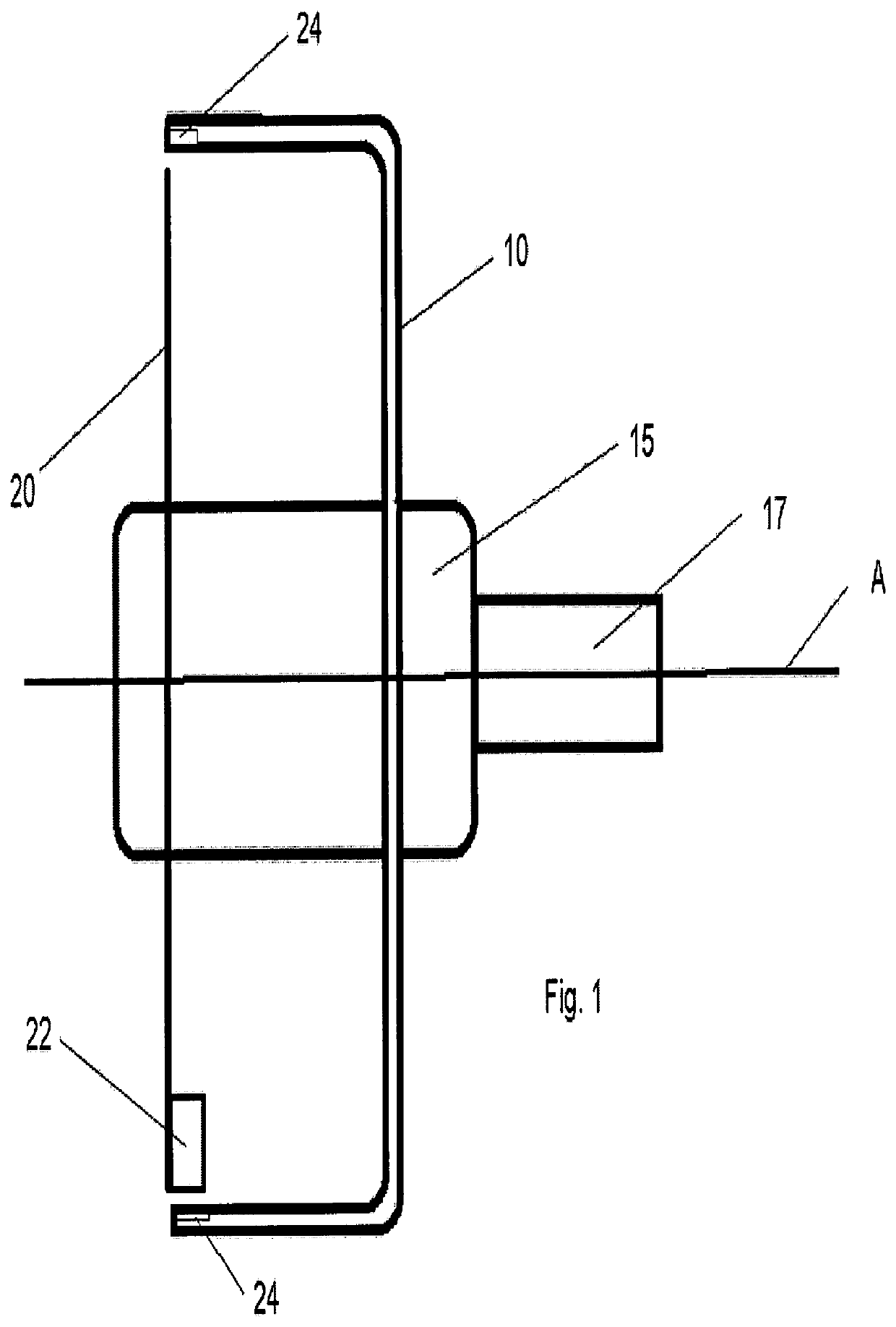
[0020]FIG. 1 shows a trailer drum 10 and hub 15, oriented with respect to a conventional backing plate 20 of a brake system (such as an electric brake for a cargo, industrial utility or RV trailer), as mounted on spindle or axle 17 for rotation about axis A. In this embodiment, the present invention includes the provision of at least one sensor 22 on the enclosed side of backing plate 20, facing the interior of drum 10. Preferably, sensor 22 is mounted near the circumferential periphery of backing plate 20, and spaced apart from the interior circumferential rim of drum 10. The interior circumferential rim of the drum 10, 110 has a cylindrical inside drum surface 114, shown in FIG. 7. The number of sensors mounted on backing plate 20, and the type of sensor device used for sensor 22 in a given application, can be selected according to the operating conditions desired to be detected, and the relative cost and reliability of a given type of sensor.

[0021]At least one detectable notch or...


PUM


Abstract

A drum braking system having a spindle and backing plate affixed thereto. The system includes a drum rotating on the spindle. The drum has an inside surface with integral notches that are machined or cast into the drum. When the brakes are applied, brake shoes are actuated to contact the inside surface to create drag between the drum and the spindle. A sensor is fixed with respect to the spindle or backing plate that detects the notches when the drum rotates about the spindle. A portion of the inside surface with the integral notches is shared with the brake shoes so that applying the brakes prevents buildup that could contact the sensor. The sensor is positioned radially to reduce the effect of drum endplay on detecting of the notches.

Description

CROSS REFERENCE TO RELATED APPLICATIONS[0001]This application is a Continuation-in-Part of U.S. application Ser. No. 16 / 350,268 filed Oct. 23, 2018, the disclosure of which is hereby incorporated by reference.BACKGROUND OF THE INVENTION[0002]The present invention relates generally to wheel sensors used to detect speed and / or other operating conditions, and more particularly, the present invention relates to wheel speed sensors for towable trailers, such as cargo, industrial utility, and recreational vehicle (RV) trailers, using electric brake systems. For antilock braking systems, the system needs to measure the wheel speed during braking to determine if a wheel becomes locked up. If the system detects a locked wheel, the system will release the braking force until the wheel begins to turn again. Other systems currently use a separate tone ring or wheel that is secured to the rotating parts, such as an axle, braking component, or wheel. A reliable method of detecting wheel speed is ...

Claims


Application Information

Patent Timeline
Patent Type & Authority Patents(United States)
IPC IPC(8): G01M17/007B60T1/06F16D51/22F16D65/10F16D65/22F16D121/20
CPCB60T1/067F16D51/22F16D65/10F16D65/22B60T2240/00F16D2121/20B60B27/0068F16D2051/001
Inventor BOLLINGER, STEVEN RAYCARRISON, MARKUS CLOYDLIEVORE, SAMUEL NEIL
Owner DEXTER AXLE CO LLC
Why Eureka
Try Eureka