Repeater mechanism with tensioned chain

a repeater and chain tensioning technology, applied in the field of repeater mechanisms, can solve the problems of wearer fully pressing the push button, variation of the load to which the hour part is subjected, repeater type not giving complete satisfaction, etc., and achieve the effect of reducing mechanical fatigu

Active Publication Date: 2021-07-27
MONTRES BREGUET
View PDF4 Cites 2 Cited by
  • Summary
  • Abstract
  • Description
  • Claims
  • Application Information

AI Technical Summary

Benefits of technology

[0051]Consequently, the chain is always tensioned, whatever the hour to be struck. The result is a reduction in the mechanical fatigue which the chain (with the assembly of mobile components) undergoes in the course of time, to the benefit of the operational reliability (and the operational life) of the mechanism.

Problems solved by technology

This type of repeater does not give complete satisfaction because the motor torque exerted by the barrel spring is not constant.
The result, during operation, is variations in the loads to which the hour part is subjected, which can generate in the latter mechanical fatigue cycles, conducive to cracking thereof.
However, this chain mechanism has a disadvantage which results from the fact that it operates on an all-or-nothing basis, i.e. whatever the hour to be struck, the wearer fully depresses the push button.
Consequently, the actuation of the barrel causes complete unwinding of the chain, whatever the angular course of the hour part.
But in all other cases, the angular course of these parts is not at maximum and the remaining course of the chain (beyond that which it adopts in the reading position of the hour part) causes slackening thereof, and floating thereof.
The result is a peak in the tension force to which the chain is subjected, which can cause shearing fatigue in the axes of the connecting links of the chain or in its fixing point on the hour part.

Method used


Image

  • Repeater mechanism with tensioned chain
  • Repeater mechanism with tensioned chain
  • Repeater mechanism with tensioned chain

Examples


Embodiment Construction

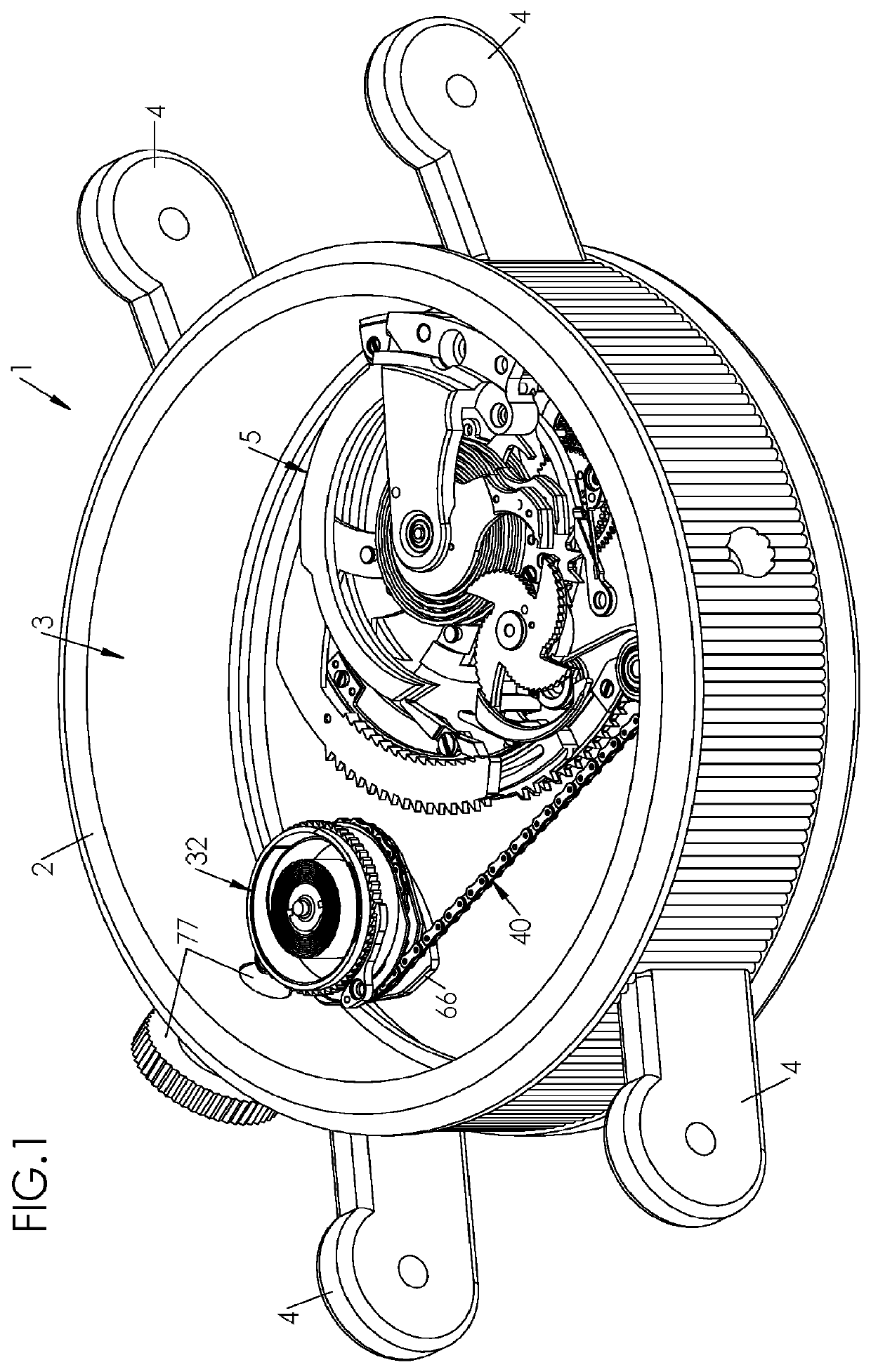
[0077]In FIG. 1, a timepiece is represented partially, in this case a watch 1. The watch 1 comprises a middle 2 which defines an internal volume 3. In the illustrated example, the watch 1 is designed for wearing on the wrist, and its middle 2 comprises, to this end, projecting horns 4, on which a strap (not illustrated) is intended to be fixed.

[0078]The watch 1 comprises a clock movement designed to indicate at least the hours and the minutes. The movement comprises a plate intended to be accommodated in the internal volume 3 defined by the middle 2, being fixed there.

[0079]The movement comprises furthermore various functional components brought together by sub-assemblies. When a sub-assembly has a different function from displaying the hours, the minutes and, if necessary, the seconds, it is termed “complication”.

[0080]Hence, the timepiece (i.e. the watch 1) which is illustrated has a striking mechanism, and comprises, for the purposes of striking the current hour, a repeater mecha...


PUM


Abstract

A repeater mechanism includes: an hour part, which is mobile between a resting position and a reading position; an hour spring that returns the hour part towards its reading position; a chain that is hooked to the hour part; a barrel that includes a shaft, a drum, a spring, a pulley that is mobile in rotation relative to the shaft and on which the chain is hooked, and also a ratchet that is integral in rotation with the barrel shaft and coupled to the pulley as long as the hour part exerts a traction force on the chain, and uncoupled from the pulley as soon as this traction force is cancelled out; and a pulley spring that is interposed between the ratchet and the pulley.

Description

[0001]This application claims priority from European Patent Application No. 17209994.7 filed on Dec. 22, 2017, the entire disclosure of which is hereby incorporated herein by reference.TECHNICAL FIELD[0002]The invention relates to the field of clockmaking. It concerns, more precisely, a repeater mechanism for a timepiece with a striking mechanism, the expression “timepiece” designating preferably a watch (wrist or fob), but likewise being able to designate a pendulum clock or even a clock.TECHNOLOGICAL BACKGROUND[0003]The repeater mechanism (currently simply named repeater) has the function, when actuated by the user (or wearer) exerting at any moment pressure on a push button, of striking the hour indicated at this moment by the hands of the timepiece.[0004]The repeater is a clockmaking complication of extreme refinement, mastery of which does credit to the clockmaker who is at the origin thereof. Formerly intended for allowing the time to be known in darkness, the repeater today e...

Claims


Application Information

Patent Timeline
Patent Type & Authority Patents(United States)
IPC IPC(8): G04B21/04G04B23/03G04B21/14G04B21/02G04B21/06G04B21/12
CPCG04B21/04G04B21/027G04B21/06G04B21/12G04B21/14G04B23/03G04B1/16G04B13/025G04B31/00
Inventor BIFRARE, CHRISTOPHEMATTEAZZI, DANIEL
Owner MONTRES BREGUET
Why Eureka
Try Eureka