
Traveling water delivery device

a water delivery device and water display technology, applied in the direction of liquid spraying apparatus, spraying apparatus, etc., can solve the problems of limited visual effects, fixed water delivery devices typically cannot provide the appearance, and most limited human dancers' movements

Active Publication Date: 2021-08-03
WET ENTERPRISES
View PDF7 Cites 0 Cited by
  • Summary
  • Abstract
  • Description
  • Claims
  • Application Information

AI Technical Summary

Benefits of technology

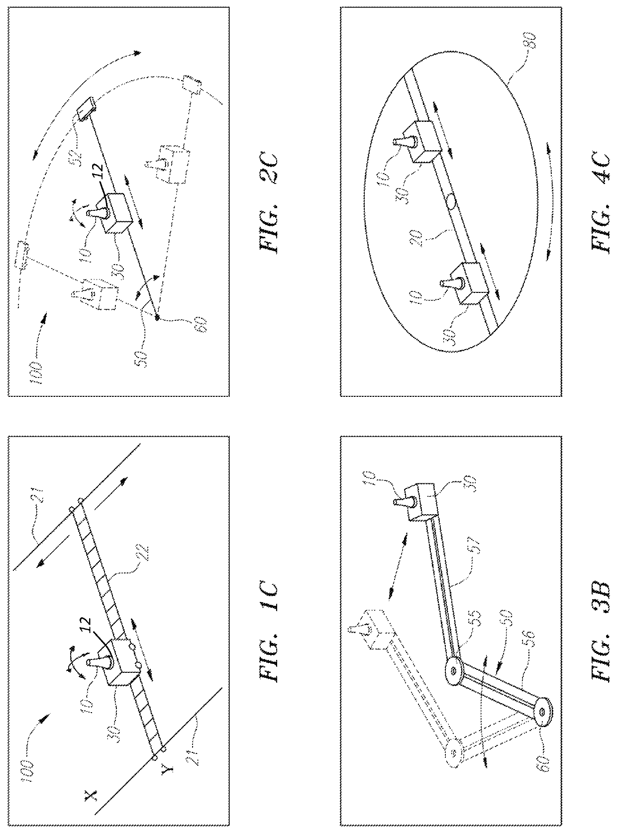
This patent describes a water display with moving water delivery devices that appear to be moving around the display reservoir. The water delivery devices can be mounted on a trolley or a small controllable underwater vehicle that moves along a track or prescribed path. The trolley may not be attached to a specific grid, making the water delivery device's path independent of any grid. The technical effects of this patent include the ability to create the impression of water delivery devices moving around the reservoir, along with different types of tracks that can be used for the movement.

Problems solved by technology

These existing water delivery devices may provide dramatic visual effects, but if they are fixed to the bottom of the water reservoir, there is some limitation of the visual effects they can produce.
For example, fixed water delivery devices typically cannot provide the appearance of a stream of water that moves to different locations in the reservoir.
However, this is an overstatement in that even the most limited human dancer moves in some form across the performance stage, whereas existing water delivery devices and nozzles, robotic or otherwise, are affixed to the ground or pool bottom and move, if they move at all, about that fixed point.

Method used


Image

  • Traveling water delivery device
  • Traveling water delivery device
  • Traveling water delivery device

Examples


Embodiment Construction

[0027]The current invention is now described with reference to the figures. Where the same or similar components appear in more than one figure, they are identified by the same reference numeral. The invention is described herein with reference to water. However, other liquids and combinations thereof are within the scope of the invention.

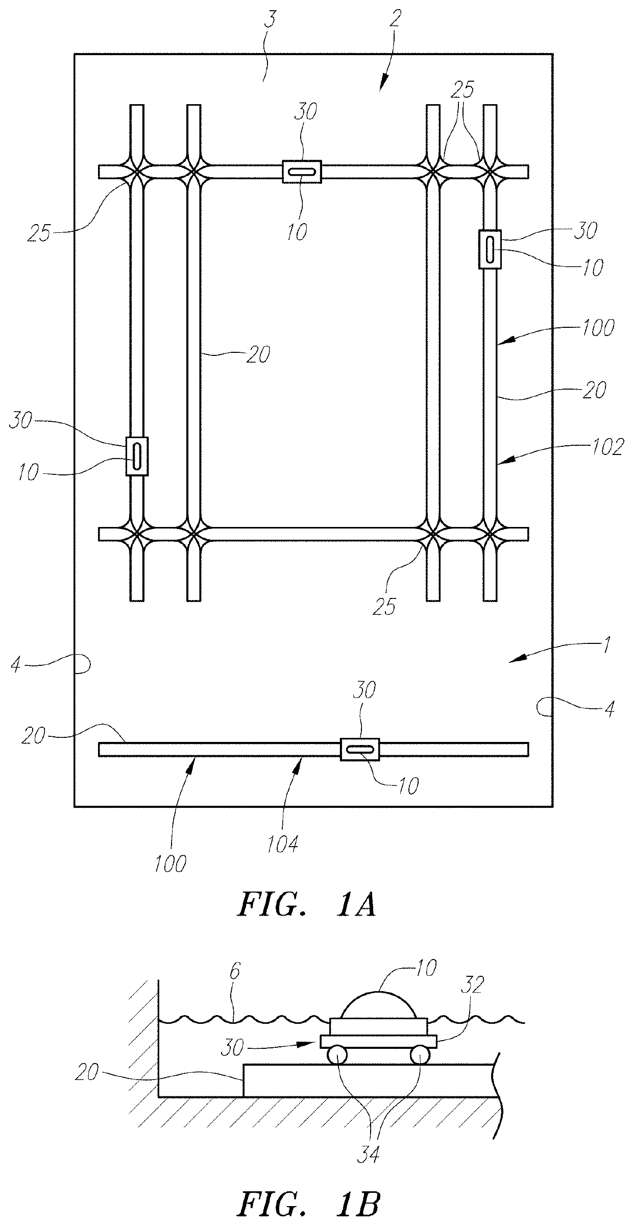
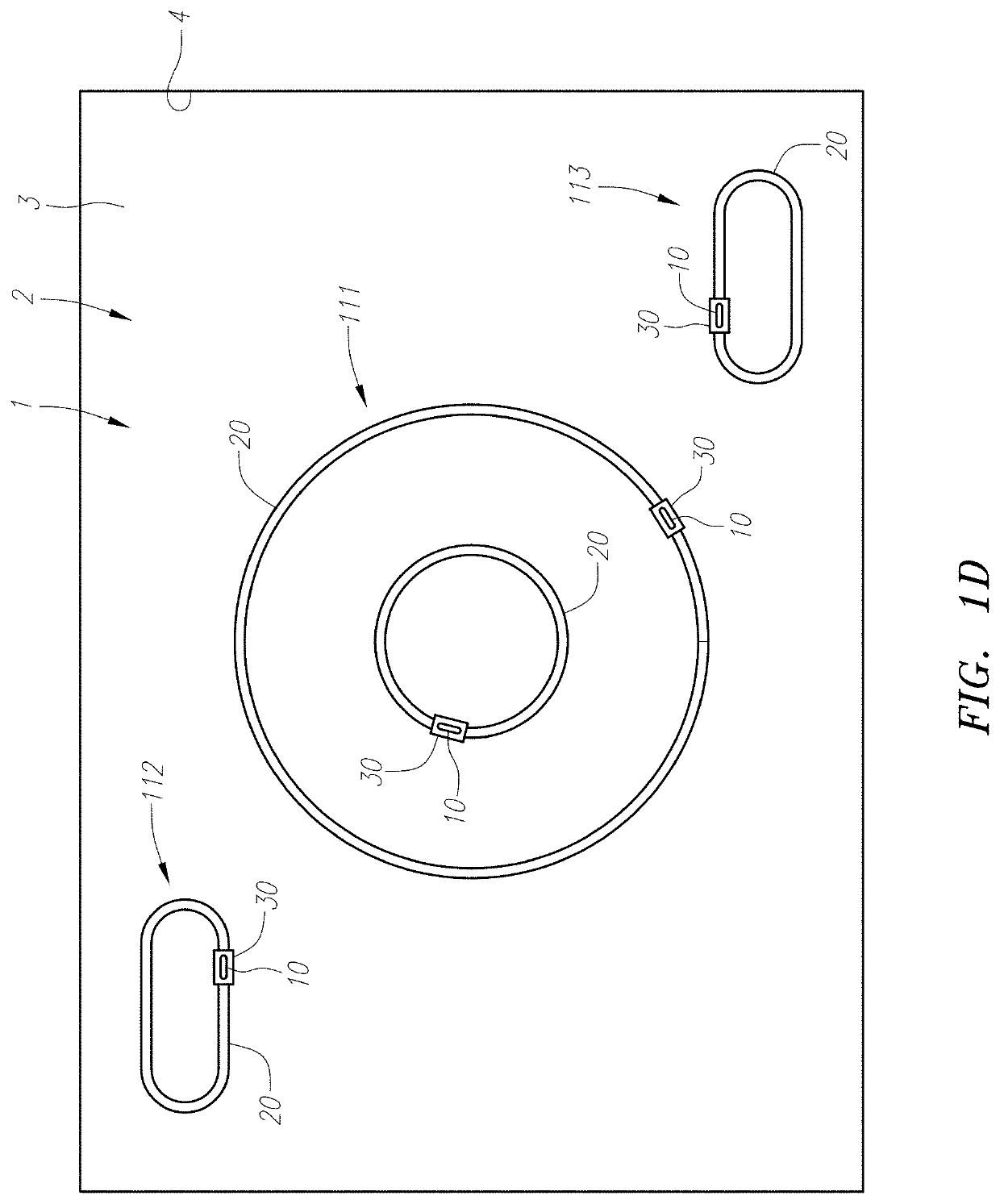
[0028]In general, one or more water delivery devices 10 of the current invention may form part of water display 1 that may be housed by pool or reservoir 2. Pool or reservoir2 may include floor 3 and walls 4. After pool 2 is filled with water 5, pool 2 generally has a water surface 6. As discussed later, FIGS. 8A-8E, 9A-9F and 10A-10F show examples of different displays 1 in reservoir 2 where the water delivery devices 10 move around. But prior to discussing the display's moving appearance, the structure is first described.

[0029]In a first embodiment, a gridded track system 100 is described with reference to FIGS. 1A, 1B and 1C. As shown in FIG. 1A...


PUM


Abstract

A device to moving a water shooter is described. The device may contain features that allow the device to travel submerged in a reservoir with a water shooter attached. The device may travel along a fixed track, rotational boom, or be free swimming in order to move the water shooter within the reservoir so that unique water effects may be achieved.

Description

CROSS REFERENCE TO RELATED APPLICATION[0001]The application claims the benefit of U.S. Provisional Application No. 61 / 801,871, filed Mar. 15, 2013, the contents of which are incorporated herein by reference.FIELD OF THE INVENTION[0002]The present invention generally relates to water displays and water delivery devices used in such display, including a water delivery device that may move during the performance of the water display.BACKGROUND OF THE INVENTION[0003]Various types of water displays exist, and many of them include various types of water delivery devices that shoot water into the air. Oftentimes, the water display is located in a reservoir having a floor and walls. Before the reservoir is filled with water, a network of water delivery devices may be attached to the bottom of the reservoir. This may include the water delivery devices themselves, as well as supporting lines such as electrical, water supply and other lines. After the reservoir is filled, water generally surro...

Claims


Application Information

Patent Timeline
Patent Type & Authority Patents(United States)
IPC IPC(8): B05B17/08B05B13/04
CPCB05B17/08B05B13/04
Inventor FULLER, MARKDOYLE, JAMESTALMOR, AMNON
Owner WET ENTERPRISES
Learn More