Key structure

a keycap and key cap technology, applied in the direction of contact mechanisms, electrical devices, electric switches, etc., can solve the problems of increasing production costs, poor hand feel, and the inability of fixing members to securely join with the base plate, so as to reduce the occurrence of shaking or shifting of the keycap when the keycap is hit, and maintain the stability of joining. the effect of stability

Active Publication Date: 2021-08-03
CHICONY ELECTRONICS
View PDF4 Cites 0 Cited by
  • Summary
  • Abstract
  • Description
  • Claims
  • Application Information

AI Technical Summary

Benefits of technology

[0004]It is a primary object of the present invention to provide a key structure capable of reinforcing the structural strength between a guiding structure and a base plate.
[0006]With a fitting force between the fixing member and the connection member, the structural strength between the guiding structure and the base plate is reinforced, thus maintaining the joining stability between the pivot shaft of the guiding structure and the connection groove, minimizing the occurrence of shaking or shifting of the key when the keycap is hit.

Problems solved by technology

If the overall structural strength of the keys thereof is insufficient, shaking or shifting of the keys can result, causing a poor hand feel when the keys are hit by a user.
Alternatively, before being shipped out of the factory, if such keyboard products fail to pass quality control inspection because the guiding structure is not securely joined with the base plate, waste and consequent increases in production costs can result.
However, due to the demand for thin and lightweight keyboards, even if the base plate becomes thinner and is additionally provided with a fixing member, the fixing member cannot be securely joined with the base plate because of the small overall thickness of the base plate as well as the insufficient joining strength between the fixing member and the base plate, which results in an insufficient joining strength between the guiding structure and the base plate.
The abovementioned issues of shaking of the keys or failure to pass quality control inspection can still result.

Method used


Image

  • Key structure
  • Key structure
  • Key structure

Examples


Embodiment Construction

[0016]To enable the Examiner to better understand the technical contents of the present invention, preferred embodiments are described in detail below.

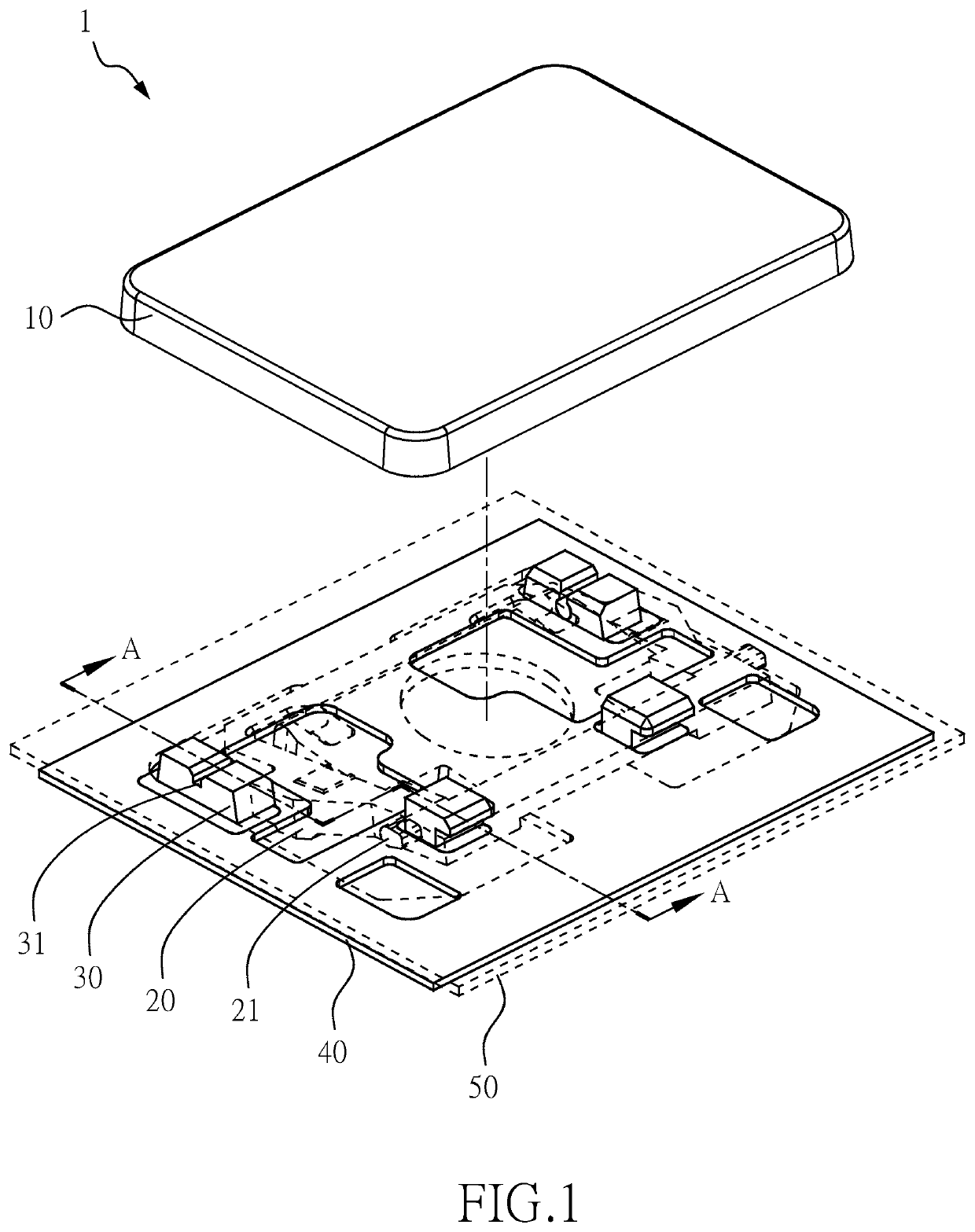
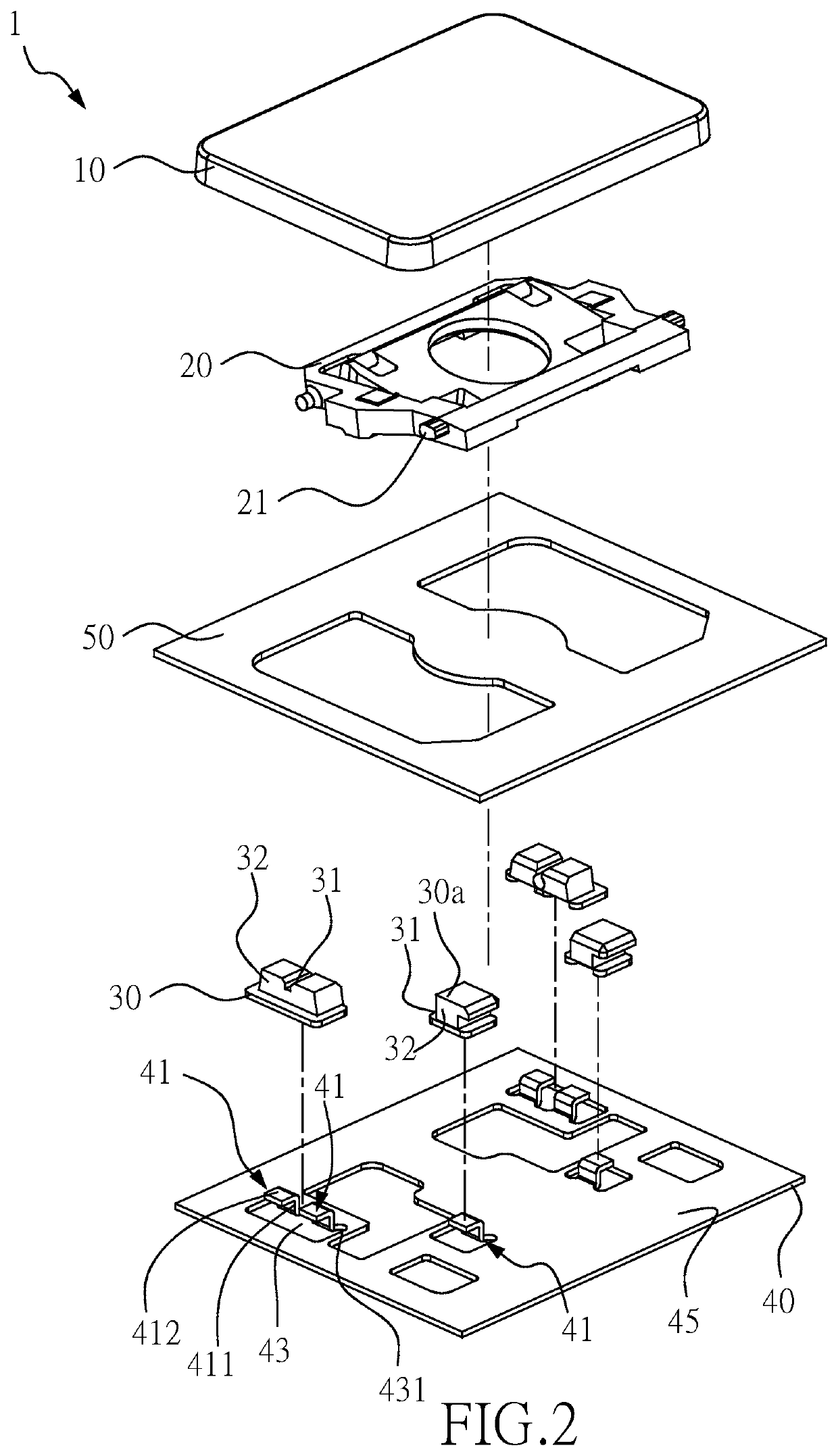
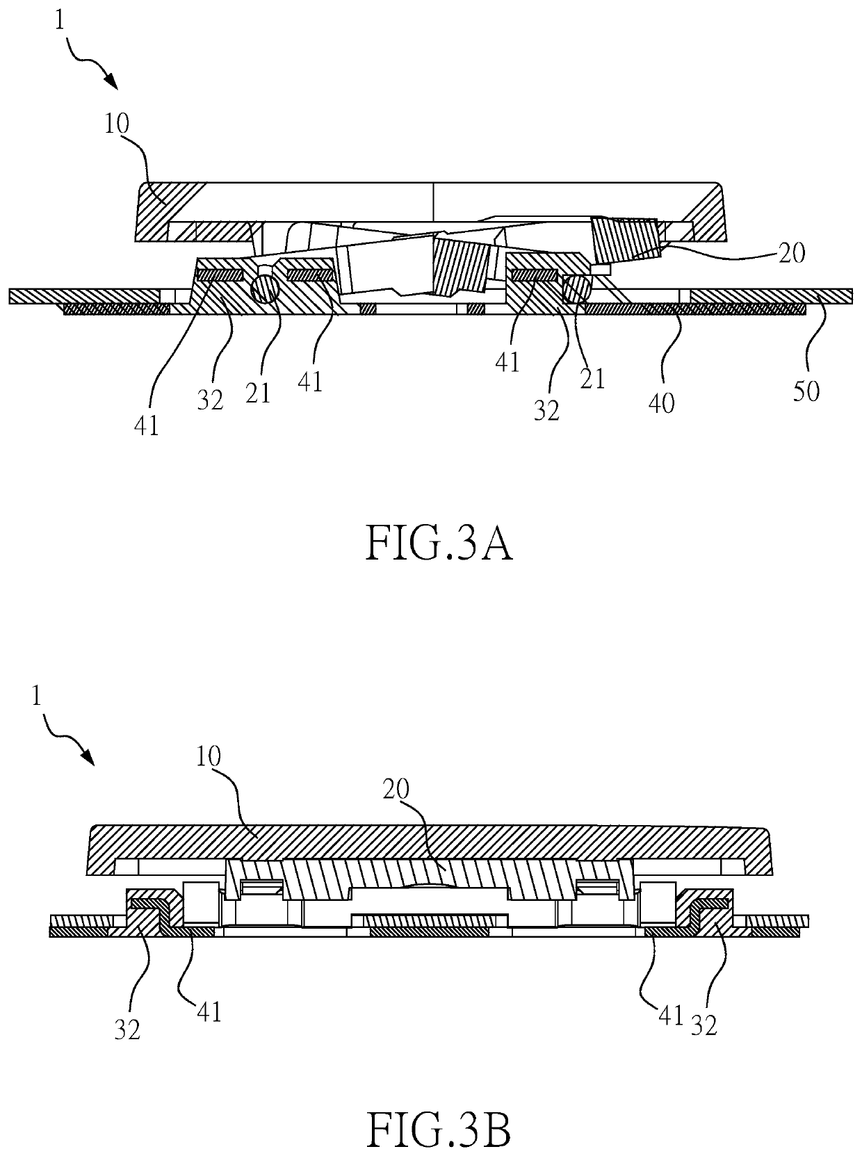
[0017]Refer to FIG. 1, FIG. 2, FIG. 3A and FIG. 3B for a schematic diagram, an exploded structural diagram, a cross-sectional diagram along the section line AA in FIG. 1 and a cross-section diagram of a key structure according to a first embodiment of the present invention.

[0018]As shown in FIG. 1, FIG. 2, FIG. 3A and FIG. 3B, in this embodiment, a key structure 1 of the present invention includes a keycap 10, a guiding structure 20, a connection member 30, a base plate 40 and a circuit board 50. The guiding structure 20 is located below the keycap 10 and includes at least one pivot shaft 21. The connection member 30 includes a connection groove 31, and the at least one pivot shaft 21 is connected to the connection groove 31, thereby fixing the guiding structure 20. The circuit board 50 is located between the base plate 40 and the gui...


PUM


Abstract

A key structure includes a keycap, a guiding structure, a connection member and a base plate. The guiding structure is located below the keycap and includes at least one pivot shaft. The connection member includes a connection groove, and the at least one pivot shaft is connected to the connection groove. The base plate includes at least one fixing member. The connection member envelops the at least one fixing member such that the connection member is fixed to the base plate.

Description

FIELD OF THE INVENTION[0001]The present invention relates to a keycap structure and, more particularly, to a keycap structure capable of reinforcing the structural strength between a guiding structure and a base plate.DESCRIPTION OF THE PRIOR ART[0002]With constant improvements in technology, electronic products have become indispensable tools to modern people. With regard to the habits of use of computer users, keyboards are essential input tools. A conventional membrane keyboard, for instance, is composed of components including a keycap, a guiding structure, a membrane circuit and a base plate. When a user hits a keycap, the keycap is guided by the guiding structure to move down and triggers the membrane circuit so as to generate an input signal. If the overall structural strength of the keys thereof is insufficient, shaking or shifting of the keys can result, causing a poor hand feel when the keys are hit by a user. Alternatively, before being shipped out of the factory, if such...

Claims


Application Information

Patent Timeline
Patent Type & Authority Patents(United States)
IPC IPC(8): H01H13/14
CPCH01H13/14H01H3/125H01H13/88H01H2229/048
Inventor CHENG, CHI-HUNGCHEN, CHIA-HSIN
Owner CHICONY ELECTRONICS
Why Eureka
Try Eureka