Receiver suspension for a hearing assisting device

a technology for hearing aides and receivers, applied in the direction of hearing aids mounting/interconnection, transducer details, electrical transducers, etc., can solve the problems of increasing the risk of receiver failure, and increasing the size of the hearing aide device on the floor, so as to improve reliability, stable position of the receiver, and good stability of the receiver's position

Active Publication Date: 2021-08-03
WIDEX AS
View PDF7 Cites 0 Cited by
  • Summary
  • Abstract
  • Description
  • Claims
  • Application Information

AI Technical Summary

Benefits of technology

[0008]An advantage of this solution is that it is possible to achieve a high resistance against mechanical shock and a low risk of feedback problems at the same time. There will be other resonance frequencies at higher frequency.
[0010]In an embodiment of the hearing assisting device, the receiver is a reduced vibration type receiver. This is defined such that at the frequencies 1 kHz, 3 kHz, 6 kHz and 8 kHz, the receiver has a maximum level of vibration at −20 dB, −10 dB, 0 dB and 10 dB, respectively, when measured in relation to 1 m / s2 / Pa for a freely suspended receiver, e.g. producing a sound pressure in a 711 coupler. Using this type of receiver in a suspension with the resonance frequency in the range of 6 kHz to 10 kHz has been found to provide a solution with almost no risk of feedback problems, and still a very high resistance against mechanical shock.
[0011]In an embodiment of the hearing assisting device, the receiver is a double receiver, i.e. a dual diaphragm receiver. This is a receiver type where the two diaphragms are balanced in order to minimize the mechanical vibrations from the receiver. A few double receivers on the market will exhibit vibration levels lower than the above mentioned maximum values pertaining to a reduced vibration type receiver, and will thus lower the risk of feedback further.
[0013]In a further embodiment of the hearing assisting device, the cross sectional shape of the receiver is rectangular or approximately rectangular, and the supporting ridges are arranged on at least two different surfaces of the receiver. A typical receiver has a box-shape with six surfaces; one surface typically reserved for electrical terminals. Another surface, typically the one opposite to the one with terminals, is provided with the sound outlet. In practice, this leaves four surfaces for suspension ridges. Having ridges on at least two surfaces secures a good stability of the receiver's position.
[0014]In a further embodiment of the hearing assisting device, ridges are arranged at or towards opposite ends of the receiver, where opposite ends are defined for the longest dimension of the receiver. This makes the position of the receiver more stable and thereby improves reliability.
[0015]In a further embodiment of the hearing assisting device, the ridges are arranged on a sleeve arranged around the receiver, the sleeve being made from the same material as the ridges, e.g. integral with the ridges. This has the advantage of being a simple and reliable way to position the ridges at the receiver.

Problems solved by technology

One problem of a hard mounted receiver is that it will be more vulnerable to damage e.g. by mechanical shock.
This means that the risk of failure of the receiver when dropping a hearing assisting device on the floor becomes considerably larger when hard mounting the receiver.

Method used


Image

  • Receiver suspension for a hearing assisting device
  • Receiver suspension for a hearing assisting device
  • Receiver suspension for a hearing assisting device

Examples


Embodiment Construction

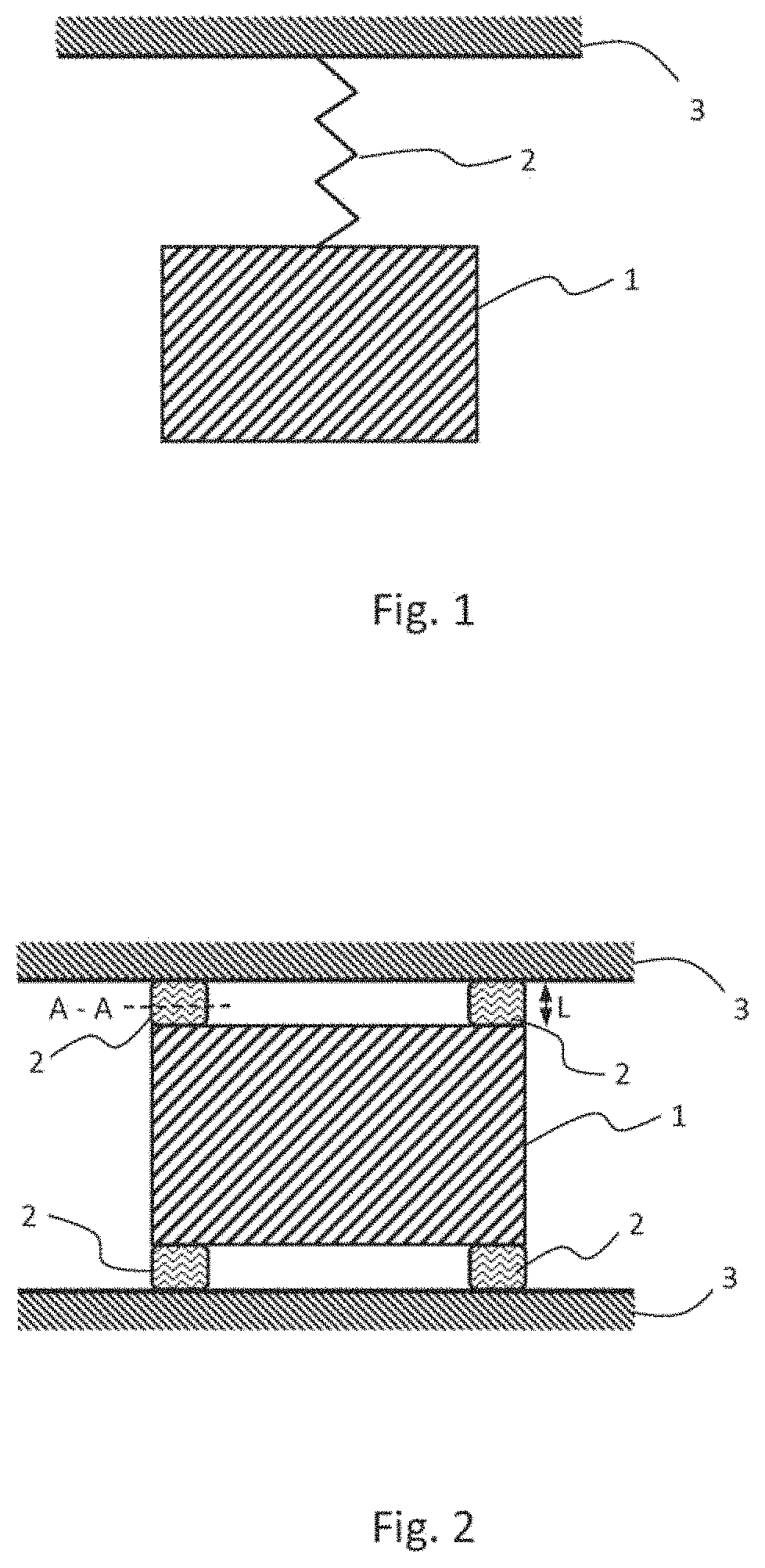
[0025]FIG. 1 shows a model of a suspended receiver 1 connected through a suspension 2 to a fixture 3. The fixture 3 could be the housing of the hearing assisting device or a structure connected to the housing. The suspension 2 is often made from a resilient material such as a rubber or a rubber like material, e.g. a silicone or butyl. The suspension 2 is in practice arranged as a number of ridges or fins extending from the receiver 1 to the fixture 3.

[0026]The stiffness S of the suspension can be found by

[0027]S=E⁢AL(1)

where E is the modulus of elasticity for the suspension material, A is the total cross-sectional area for the ridges or fins suspending the receiver. L is the height of the ridges.

[0028]FIG. 2 shows a practical example of the suspension, where the suspension comprises four ridges 2 squeezed between the fixture 3 and the receiver 1. The ridges hold on to the receiver by a combination of compression and surface friction. On one of the ridges (the upper left) the plane A...


PUM


Abstract

A hearing assisting (10) device including a receiver (1) for generation of acoustic signals and a fixture (3, 8, 9) for positioning the receiver. A suspension (2, 21, 22) supports the receiver to the fixture. The combination of the receiver and the suspension has a mechanical resonance frequency in the range from 6 kHz to 10 kHz.

Description

CROSS REFERENCE TO RELATED APPLICATIONS[0001]This application is a National Stage of International Application No. PCT / EP2016 / 057226 filed Apr. 1, 2016.BACKGROUND OF THE INVENTION[0002]The present invention relates to a hearing assisting device. The invention more specifically relates to a hearing assisting device comprising a receiver for generation of acoustic signals and a fixture for positioning the receiver, wherein a suspension supports the receiver within the fixture.[0003]It is well known to arrange a receiver for a hearing assistive device, such as a hearing aid, in a suspension in order to dampen mechanical vibrations from the receiver housing and thereby reducing any feedback to the microphone. Such a solution is e.g. illustrated in U.S. Pat. No. 7,088,839 B2.[0004]When applying special low vibration receivers it is possible to hard-mount the receiver, i.e. mounting it directly to the structure in the hearing aid, e.g. directly to the hearing aid housing, without any susp...

Claims


Application Information

Patent Timeline
Patent Type & Authority Patents(United States)
IPC IPC(8): H04R25/00
CPCH04R25/456H04R25/60H04R2225/025H04R2225/57H04R1/2873H04R25/604
Inventor FRIIS, LARSBURGER, CHRISTIAN CHRISTIANSENSVEJGAARD, CHRISTIAN LYNGSOETOPHOLM, JANDUE, RUNE AARUPLINANDER, TOKE BORGENANDERSEN, CHRISTIAN
Owner WIDEX AS
Why Eureka
Try Eureka