Jack hammer silica dust suppression system

a technology of dust suppression system and jack hammer, which is applied in the direction of percussive tools, chemistry apparatus and processes, manufacturing tools, etc., can solve the problems of insufficient implementation of solutions, large equipment volume, and inability to meet the needs of workers,

a technology of dust suppression system and jack hammer, which is applied in the direction of percussive tools, chemistry apparatus and processes, manufacturing tools, etc., can solve the problems of insufficient implementation of solutions, large equipment volume, and inability to meet the needs of workers,

US11103988B2Active Publication Date: 2021-08-31CJ&S INC

Image

  • Jack hammer silica dust suppression system
  • Jack hammer silica dust suppression system
  • Jack hammer silica dust suppression system

Examples


Embodiment Construction

[0028]For purposes of the description hereinafter, the terms “end”, “upper”, “lower”, “right”, “left”, “vertical”, “horizontal”, “top”, “bottom”, “lateral”, “longitudinal”, and derivatives thereof shall relate to the invention as it is oriented in the drawing figures. However, it is to be understood that the invention may assume various alternative variations and step sequences, except where expressly specified to the contrary. It is also to be understood that the specific devices and processes illustrated in the attached drawings and described in the following specification are simply exemplary embodiments or aspects of the invention. Hence, specific dimensions and other physical characteristics related to the embodiments or aspects disclosed herein are not to be considered as limiting.

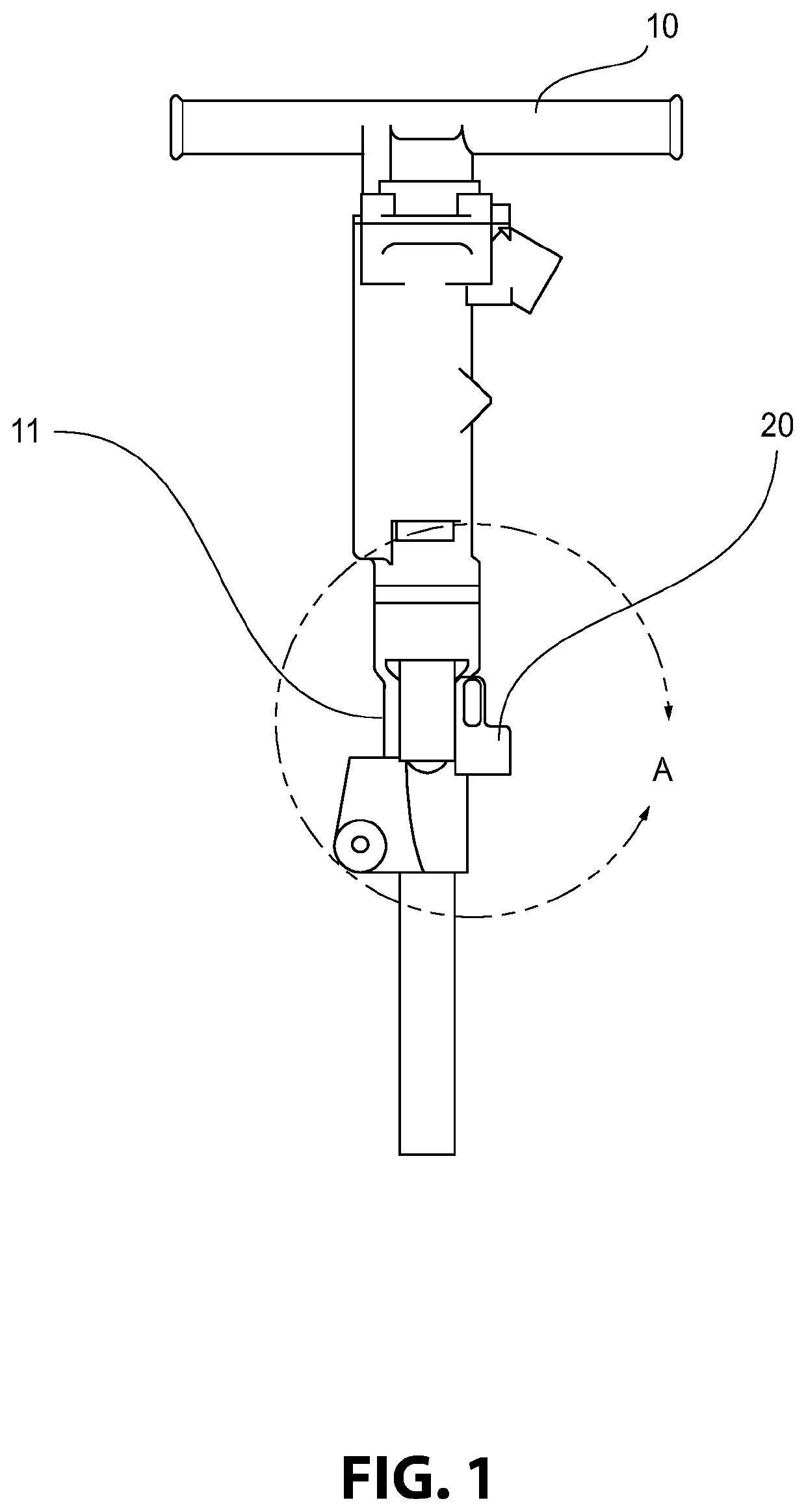
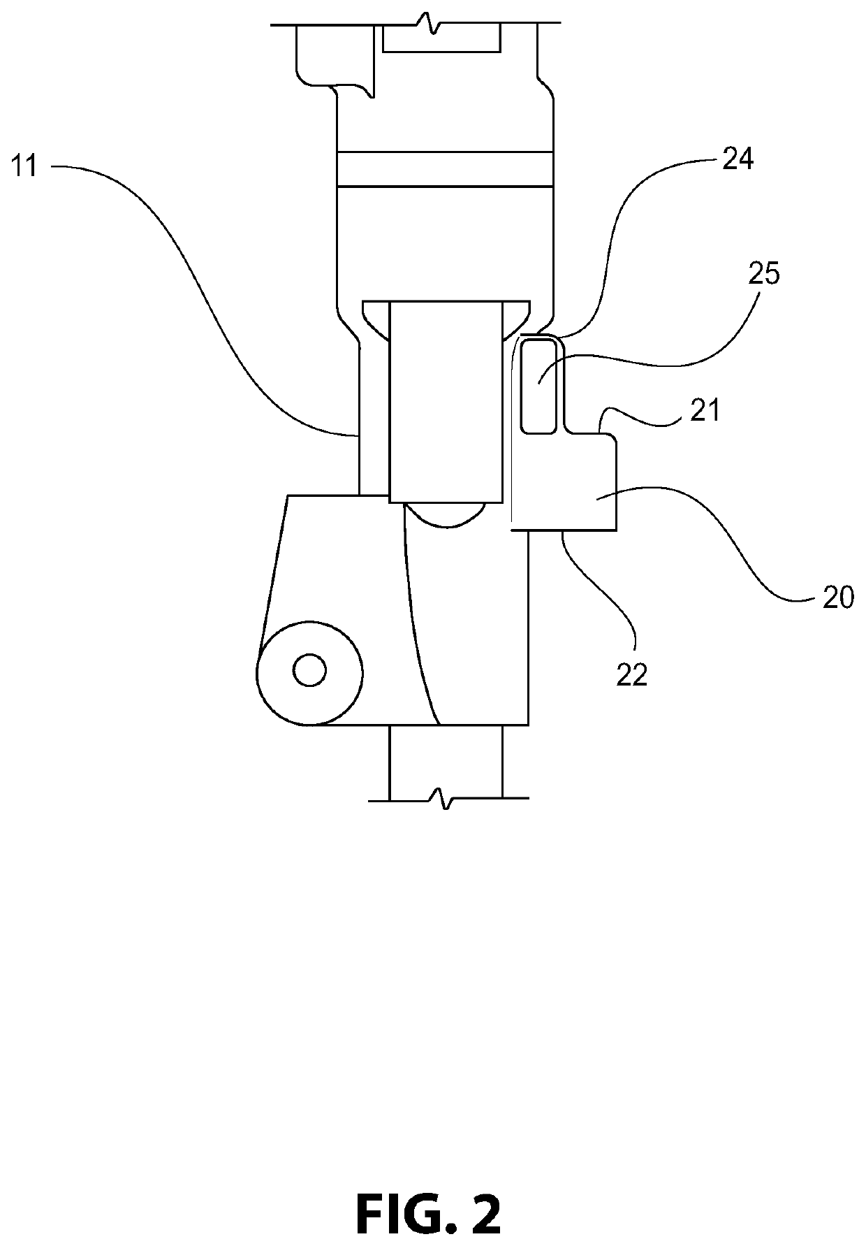
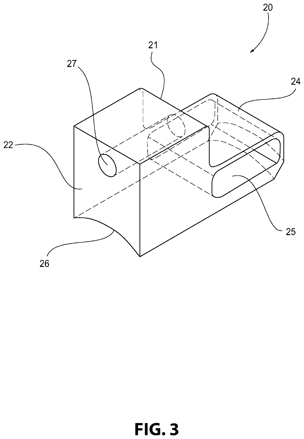
[0029]With reference to FIGS. 1-6 and 8, a dust suppression system 100 for a jack hammer 10 is shown in accordance with an example of the present disclosure. The system 100 includes a spraying device...


PUM


Abstract

A dust suppression system for a jack hammer includes a spraying device that applies a fluid spray to an area surrounding the jack hammer. The spraying device includes a bracket connected to the jack hammer and a nozzle that creates the fluid spray. The system also includes a fluid source and a pump in fluid communication with the fluid source and the spraying device. The pump directs fluid from the fluid source to the spraying device. The bracket directs fluid from the pump and the fluid source to the nozzle.

Description

CROSS REFERENCE TO RELATED APPLICATIONS[0001]The present application claims priority from U.S. Provisional Patent Application No. 62 / 582,110, filed on Nov. 6, 2017, which is hereby incorporated by reference in its entirety.BACKGROUND OF THE INVENTIONField of the Invention[0002]The invention relates to a dust suppression system for a jack hammer and, in particular, a dust suppression system incorporating a fluid-spraying device connected to the jack hammer by a bracket.Description of Related Art[0003]Concrete, masonry, and many stone products contain crystalline silica. When a jack hammer is utilized to break up these materials for standard maintenance, re-construction of existing structures, or new construction, a large amount of dust containing crystalline silica particles can be created. This airborne silica dust poses a risk to workers, as exposure may result in the development of certain debilitating lung diseases, such as silicosis.[0004]Recent regulations enacted by the Occupa...

Claims


Application Information

Patent Timeline
31 Aug 2021
Publication
US11103988B2
IPC
B25D17/22; B23Q11/00; B05B9/04
CPC
B25D17/22; B05B9/0426; B23Q11/0042; B25D2217/0057; B08B17/00; B05B15/62
Inventors
SCIGLIANO, NATHAN; LIVENGOOD, CHRIS