Wind turbine generator for low to moderate wind speeds

a wind turbine generator and low-to-moderate wind technology, applied in the direction of machines/engines, mechanical energy handling, mechanical equipment, etc., can solve the problems of limiting the overall ability of the three-bladed rotor to between about 231-241 watts per square, negating the advantages associated with any increase in efficiency, etc., to achieve efficient conversion of torque into electrical power, high density, and high moment force

Active Publication Date: 2021-08-31
21ST CENTURY WIND INC
View PDF21 Cites 0 Cited by
  • Summary
  • Abstract
  • Description
  • Claims
  • Application Information

AI Technical Summary

Benefits of technology

[0007]The relatively shorter and wider aerodynamic blades result in a rotor having a specific power of between about 0.25 and 0.29, a specific power rating of between about 240 and 260 watts / m2, and a solidity of between about 5% and 6%. Each of the blades preferably includes an aerodynamic surface over its entire length from a proximal end that is mounted on the modular hub to its distal end. In a preferred embodiment, each blade includes a blade portion having a length that terminates in the blade tip; a blade root connected between the blade portion, and the hub, and an aerodynamic fairing that covers the length of the blade root such that the entire length of the blade includes an aerodynamic, energy-generating surface. The tip end of each blade may include a rearward blade sweep to increase the energy-capturing area The blade root is preferably formed from a material such as rolled steel that is less flexible than the material forming the blade portion to prevent the higher moment forces applied to the relatively shorter and wider blades during high-wind conditions from bending the blades to the extent that they collide with the support tower. The length of the blade root is between about 20% and 30% of the over-all length of the blade so that the stiffening that the blade root imparts to the overall blade is substantial. The length of each of the aerodynamic blades is preferably no more than about 65 meters to facilitate the transportation and assembly of the wind turbine generator. The tip end of each blade may include a rearward blade sweep to increase the energy-capturing area without extending the length of the blade. Surprisingly, the applicant has observed that such a wider blade is substantially better in converting low winds having speeds of less than 7.5 m / s into electrical power than conventional, relatively longer and thinner blades, which in turn results in a higher-than-expected energy output.
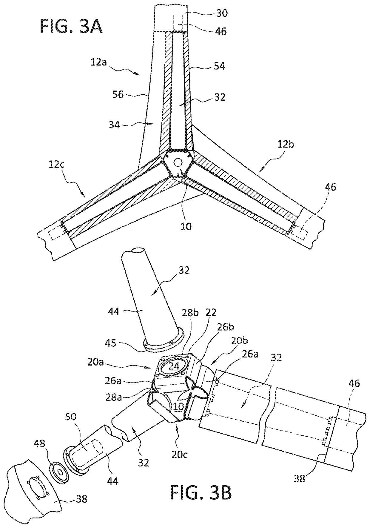
[0009]The use of a plate-type modular hub in combination with the stiff blade roots advantageously overcomes the problems associated with the use of the relatively wider blades used in the wind turbine of the invention. While the wider blades produce higher moment forces at the hub than conventional, narrower blades of the same length, the bends in the plates forming the hub sections act like corrugations that more strongly resist the resulting flexing of the blades toward the support tower of the wind turbine generator than the partial spherical-shell of steel used in conventional hub designs. These features, in combination with the stiffening of the blades of the invention through the use of a steel blade root that is between 20% and 30% of the overall length of the blade, prevent the blades from flexing to the point of colliding with the support tower even under sustained gusts of abnormally high winds.
[0010]The wind turbine generator may further comprise a nacelle including a support plate, and a gear train to an input shaft of a generator. A drive shaft connected between the hub and an input shaft of the gear train transmits the torque generated by the rotor to the gear train and generator. Preferably, the drive shaft is rotatably supported by a pair of spaced-apart bearings mounted on the support plate that are configured to isolate the input shaft of the gear train from bending forces applied to the distal end of the drive shaft by the plurality of aerodynamic blades. Additionally, the generator housed within the nacelle is preferably a high density, permanent magnet generator as such generators more efficiently convert torque into electrical power at the lower rotational speeds associated with low to moderate winds. This characteristic of a permanent magnet generator also allows the use of a simpler, planetary gear type gear train having a gear ratio on the order of 1:10 which is more reliable and robust and which requires less maintenance than the 1:100 gear ratio drive trains used in most prior art wind turbine generators.
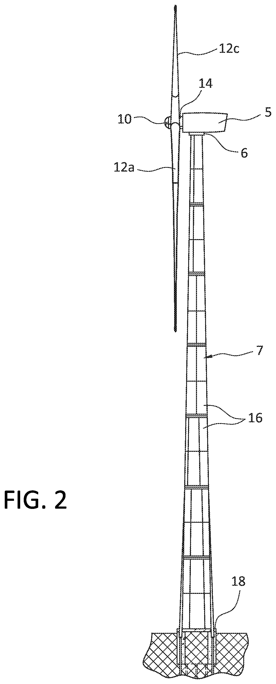
[0011]The support tower of the wind turbine generator is preferably a low-weight, modular plate-type support tower. Additionally, the ratio of the diameter d of the yaw bearing that defines the diameter of the top end of the support tower and the diameter D of the bottom end of the support tower just above the foundation is preferably between about 1.7 to 2.1. By contrast, in prior art support towers, this ratio is no more than about 1.37. Such proportioning of the upper and lower diameters d and D lowers the pressure that the inventive wind turbine generator 1 applies to the foundation by about 50%, since the weight of the wind turbine generator is distributed over twice the area of a conventional wind turbine generator. The use of a lower weight modular, plate-type support tower lowers the overall weight of the support tower typically by about 50,000 pounds, such that the pressure applied by the wind turbine generator to the foundation is reduced by an additional 16%. The resultant lower pressure not only allows the thickness of the foundation to be reduced 60% to 66%, but also allows relatively low-cost, conventional concrete to be used instead of high-cost, high-pressure rated concrete. The substantially thinner foundation also substantially reduces the over-all amount of concrete needed to construct the foundation. This not only reduces the labor and material costs of construction, but also minimizes the amount of water runoff associated with the foundation, as the substantially smaller foundation allows more of the surrounding terrain to maintain its water absorbency. All of these factors are particularly important for the wind turbine generator of the invention, which will likely be constructed on ridges or other high terrain in order to gain exposure to the highest winds in the low-to-moderate wind areas where these turbines are to be built.
[0012]Finally, none of the power conditioning components of the wind turbine generator of the invention are located within the support tower. Instead, these components are located in a separate building outside of the wind turbine generator. Such a design advantageously removes the sensitive power conditioning equipment that converts the DC current generated by the permanent magnet generator into usable AC current from the mechanical shocks and vibration present within the support tower, thereby reducing the need for maintenance and prolonging the life of this equipment.

Problems solved by technology

While such a design is capable of generating significant power in low to moderate wind speeds of between 6.0 and 7.5 m / s, the applicant has observed a number of shortcomings in such a design strategy that limits it overall ability to efficiently convert wind to electrical energy.
First, the long, narrow aspect ratio of conventional blades used in such designs limits the specific power of the three-bladed rotor to between about 231-241 watts per square meter (W / m2).
The resulting stresses on the hub and bending forces applied to the drive shaft would accelerate the fatigue and wear on the hub as well as the gears within the gearbox such that the resulting additional maintenance expenses would negate the advantages associated with any increases in efficiency.
Second, the applicant has observed that the wound coil-type generators used in prior art wind turbines lose a substantial amount of efficiency at the lower rotor speeds associated with the lower wind speeds.
However, such a solution would render the gearbox more vulnerable to damage if wider blades were used due to the increased bending forces associated with such wider blades.
Such increased bending forces would cause the internal gears of the gear box attached to the rotor drive shaft to periodically squeeze against other gears or shafts, thereby accelerating wear and maintenance procedures.
Finally, the applicant has observed that the one-piece, cast hubs used in wind multi MW turbines are often so large and heavy that they cannot be cost-effectively transported to many moderate to low wind areas.
Even when such transportation is feasible, the need to raise such heavy single-piece cast hubs to the top of the support tower makes assembly of the wind turbine difficult.
Single-piece cast hubs are difficult to manufacture because of their large size, and must be rejected upon final inspection if any one portion does not conform to specification.
Consequently, such conventional, single-piece cast hubs have a high manufacturing rejection rate of nearly 50%.

Method used


Image

  • Wind turbine generator for low to moderate wind speeds
  • Wind turbine generator for low to moderate wind speeds
  • Wind turbine generator for low to moderate wind speeds

Examples


Embodiment Construction

[0033]With reference to FIGS. 1 and 2, the wind turbine generator 1 of the invention generally comprises a rotor 3, a nacelle 5 containing a gearbox and a generator, and a support tower 7 formed from a plurality of interconnectable plates 16. The bottom end of the support tower is mounted on a disc-shaped foundation 18 buried in the surrounding soil. The nacelle 5 is rotatably connected to the top end of the support tower by means of a yaw bearing 6. The rotor 3 and nacelle 5 are maintained in an orthogonal orientation with respect to the wind by means of the yaw bearing 6 and yaw motors (not shown) contained within the nacelle 5.

[0034]The rotor 3 includes a hub 10, three blades 12a, 12b, and 12c angularly spaced 120° from one another, and a driveshaft 14. The driveshaft 14 is connected at one end to the hub 10, and to the gearbox (not shown in FIGS. 1 and 2) within the nacelle 5.

[0035]With reference now to FIGS. 1, 3A, and 3B, the hub 10 is a modular hub formed from three interconn...


PUM


Abstract

A 3 megawatt wind turbine generator having a rotor configured to efficiently extract power from low to moderate winds having an average speed of between about 7.5 and 8.5 meters / second is provided. The rotor includes three aerodynamic blades having an aspect ratio of 15 mounted on a modular hub. The relatively shorter and wider aerodynamic blades result in a rotor having a specific power of about 0.27, a specific power rating of about 260 watts / m2, and a solidity of about 6%. The modular hub is formed from three interconnected hub sections, each of which formed from a single plate of spring steel bent along its sides into a modular shape. The bends in the plates forming the hub sections act like corrugations that more strongly resist the larger stresses applied to the hub as a result of the relatively shorter and wider aspect of the aerodynamic blades.

Description

FIELD OF THE INVENTION[0001]This invention relates to wind turbine generators, and is specifically concerned with a wind turbine generator having a rotor configured to efficiently extract power from low to moderate winds having an average speed of between about 7.5 and 8.5 meters / second.BACKGROUND OF THE INVENTION[0002]Wind turbine generators constitute an important and growing segment of renewable energy production, and energy production in general. In July of 2008, the U.S. Department of Energy published a report outlining a goal of increasing wind energy's contribution to the U.S. energy supply to 20% by 2030. Some states have outlined even more ambitious plans. In October of 2015, Governor Brown of California signed legislation requiring 50% of that state's energy to come from renewable energy sources, with wind energy being a substantial contributor to the increase. In his State of the State address in January of 2019, Governor Cuomo of New York proposed quadrupling that state'...

Claims


Application Information

Patent Timeline
Patent Type & Authority Patents(United States)
IPC IPC(8): F03D15/00F03D7/02F03D80/70F03D9/25H02K7/116H02K7/18
CPCF03D15/00F03D7/0224F03D9/25F03D80/70H02K7/116H02K7/1838F03D1/0675F05B2240/311Y02E10/72
Inventor MILLER, WILLIAMHANSEN, PEDER MØRCK
Owner 21ST CENTURY WIND INC
Why Eureka
Try Eureka