
Quality of service dirty line tracking

a technology of service and line tracking, applied in the field of quality of service dirty line tracking, can solve the problems of large amount of area, thread class information in the cache lines in a potentially large level three (l3) cache might be stale,

Active Publication Date: 2021-08-31
ADVANCED MICRO DEVICES INC
View PDF16 Cites 1 Cited by
  • Summary
  • Abstract
  • Description
  • Claims
  • Application Information

AI Technical Summary

Problems solved by technology

This leads to additional information being stored in the cache which can consume a large amount of area.
When this happens, the thread class information in the cache lines in a potentially large level three (L3) cache might be stale.

Method used


Image

  • Quality of service dirty line tracking
  • Quality of service dirty line tracking
  • Quality of service dirty line tracking

Examples


Embodiment Construction

[0011]In the following description, numerous specific details are set forth to provide a thorough understanding of the methods and mechanisms presented herein. However, one having ordinary skill in the art should recognize that the various implementations may be practiced without these specific details. In some instances, well-known structures, components, signals, computer program instructions, and techniques have not been shown in detail to avoid obscuring the approaches described herein. It will be appreciated that for simplicity and clarity of illustration, elements shown in the figures have not necessarily been drawn to scale. For example, the dimensions of some of the elements may be exaggerated relative to other elements.

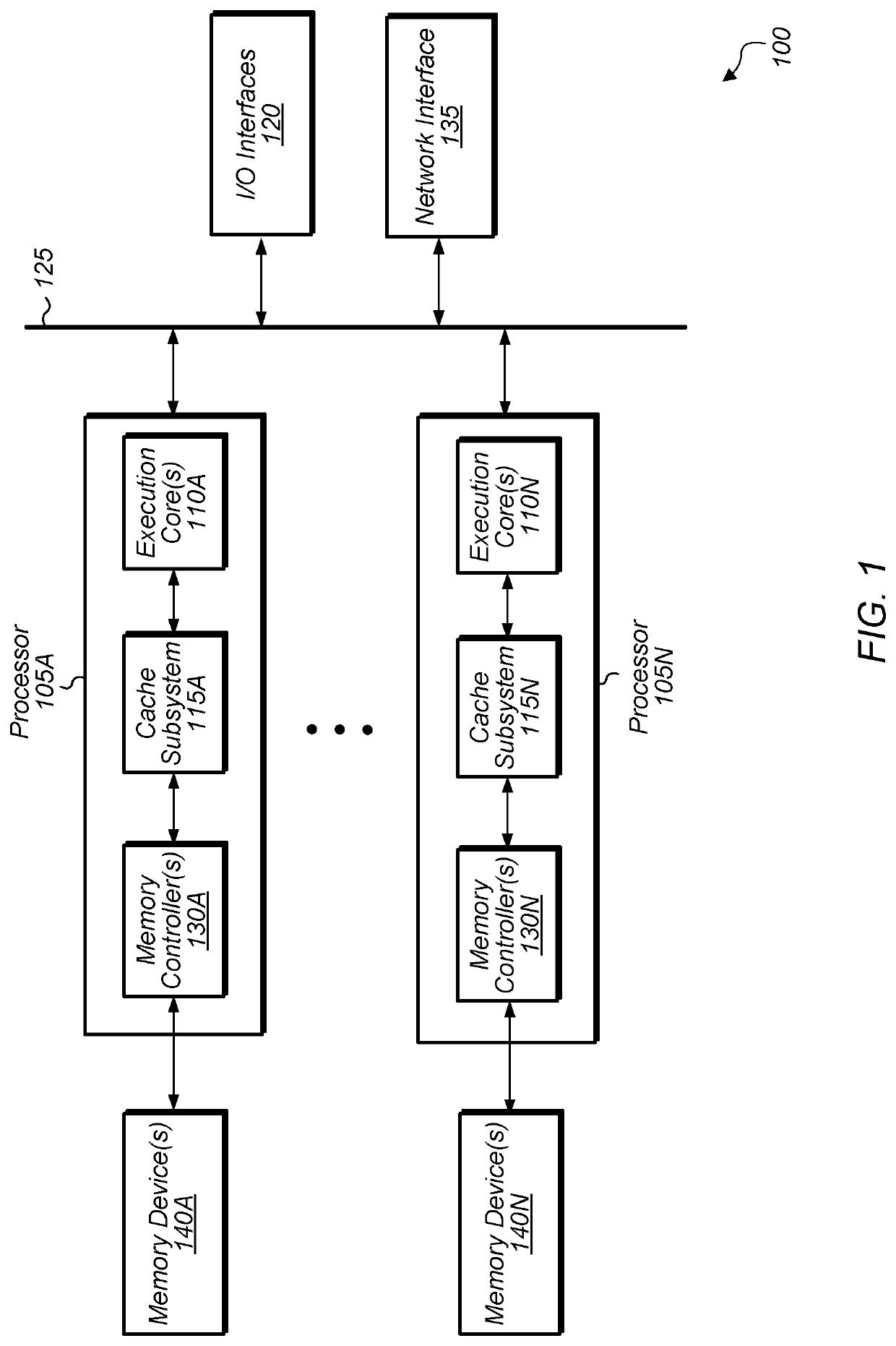
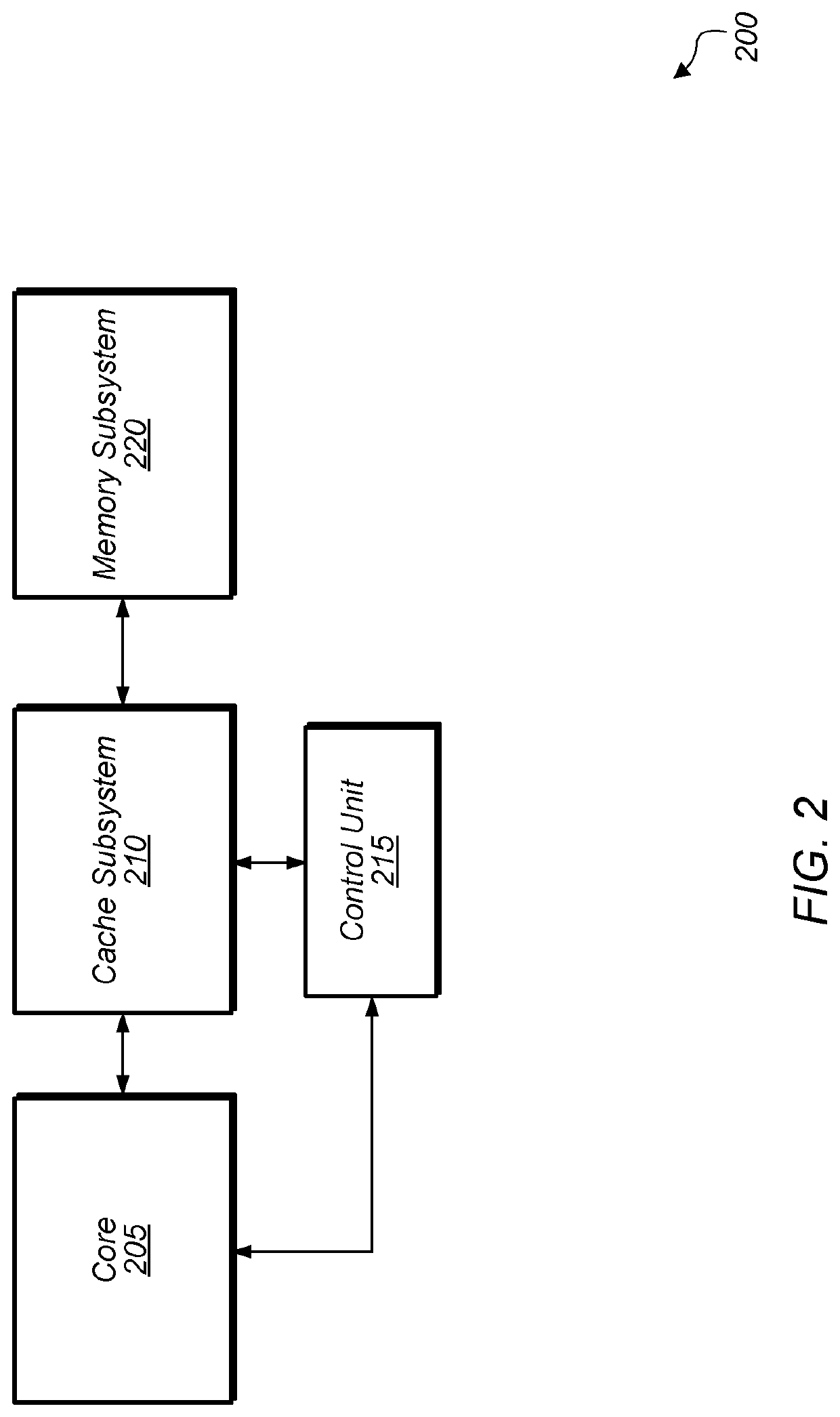
[0012]Various systems, apparatuses, methods, and computer-readable mediums for measuring write memory bandwidth are disclosed herein. In one implementation, a system includes a processor, a cache hierarchy, and a memory subsystem. The cache hierarchy includes...


PUM


Abstract

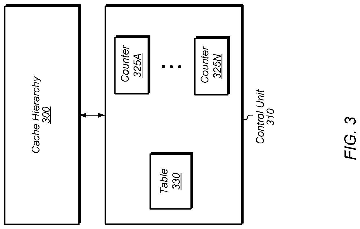
Systems, apparatuses, and methods for generating a measurement of write memory bandwidth are disclosed. A control unit monitors writes to a cache hierarchy. If a write to a cache line is a first time that the cache line is being modified since entering the cache hierarchy, then the control unit increments a write memory bandwidth counter. Otherwise, if the write is to a cache line that has already been modified since entering the cache hierarchy, then the write memory bandwidth counter is not incremented. The first write to a cache line is a proxy for write memory bandwidth since this will eventually cause a write to memory. The control unit uses the value of the write memory bandwidth counter to generate a measurement of the write memory bandwidth. Also, the control unit can maintain multiple counters for different thread classes to calculate the write memory bandwidth per thread class.

Description

BACKGROUNDDescription of the Related Art[0001]Most modern computing devices provide at least one level of cache memory (or cache) in addition to a main memory in the computing device. Generally, caches are smaller-capacity, faster-access memories that are used for storing a limited number of copies of data and instructions to be used for performing various operations nearer to the functional blocks in the computing device that perform the operations. Caches are typically implemented using higher-speed memory circuits, such as static random access memory (SRAM) integrated circuits or other types of memory circuits. When a processor requests access to data stored in memory, the processor first determines whether a copy of the data is stored in the cache. If so, the processor accesses the cache, facilitating a more efficient accessing of the data.[0002]In some caches, the class or thread associated with a cache line is stored in the cache. This leads to additional information being sto...

Claims


Application Information

Patent Timeline
Patent Type & Authority Patents(United States)
IPC IPC(8): G06F12/0891G06F9/30G06F9/38G06F12/0811
CPCG06F12/0891G06F9/3009G06F9/3816G06F12/0811G06F12/126G06F12/0897G06F12/0804G06F12/084
Inventor MOYER, PAUL JAMESHUNT, DOUGLAS BENSON
Owner ADVANCED MICRO DEVICES INC
Learn More