Ultrasonic image pickup device and image processing device
a pickup device and ultrasonic imaging technology, applied in ultrasonic/sonic/infrasonic image/data processing, image enhancement, instruments, etc., can solve the problems of difficult three-dimensional alignment, heavy burden on users, and high burden on users
- Summary
- Abstract
- Description
- Claims
- Application Information
AI Technical Summary
Benefits of technology
Problems solved by technology
Method used
Image
Examples
embodiment 1
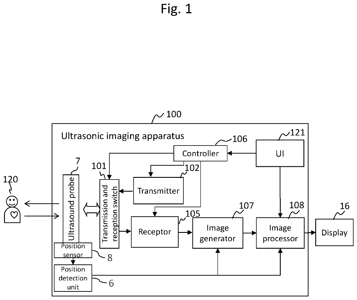
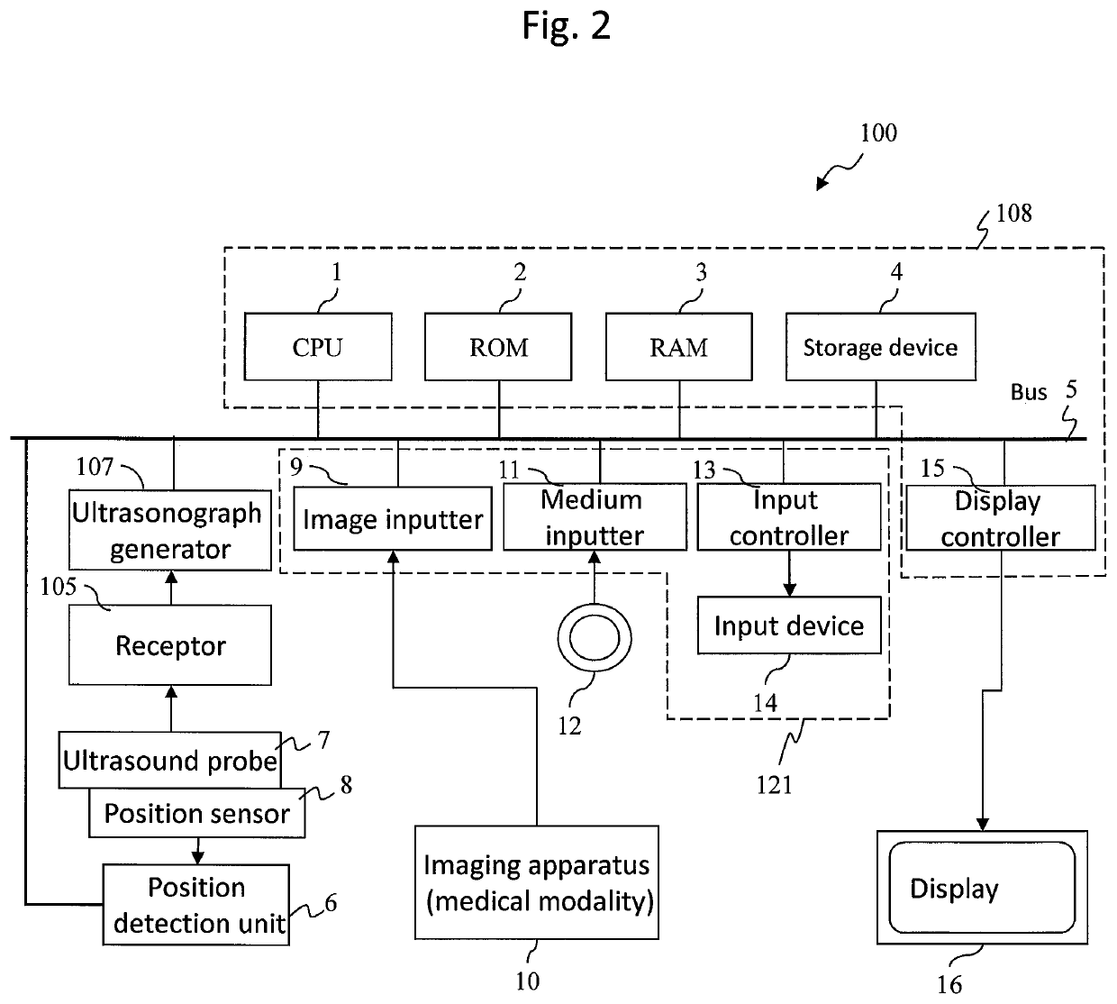
[0031]As for the configuration of the ultrasonic imaging apparatus of the present invention, the apparatus comprises, for example, an ultrasound probe 7, a position sensor 8, an image generator 107, and an image processing device 108, as shown in FIG. 1. The ultrasound probe 7 transmits ultrasonic waves to a subject 120, and receives ultrasonic waves reflected by the subject 120. The position sensor 8 is attached to the ultrasound probe 7. The image generator 107 generates an ultrasonograph from the signals received by the ultrasound probe 7, and generates first volume data from the ultrasonograph and positional information of the ultrasound probe 7 obtained from the position sensor 8. The image processing device 108 receives second volume data obtained by another external imaging apparatus for the subject 120, and processes them. For this processing, the image processing device 108 carries out alignment of the first volume data and the second volume data. The image processing devic...
embodiment 2
[0066]In the embodiment 1, CT volume data are initially rotated by a rotation angle obtained beforehand for each zone of internal organ. However, the present invention is not limited to such a configuration, and the angle for the initial rotation can also be obtained by calculation. This configuration will be explained as the embodiment 2. In the explanation of the embodiment 2, the same configurations and processings as those of the embodiment 1 are indicated with the same numerals, and explanations thereof are omitted.
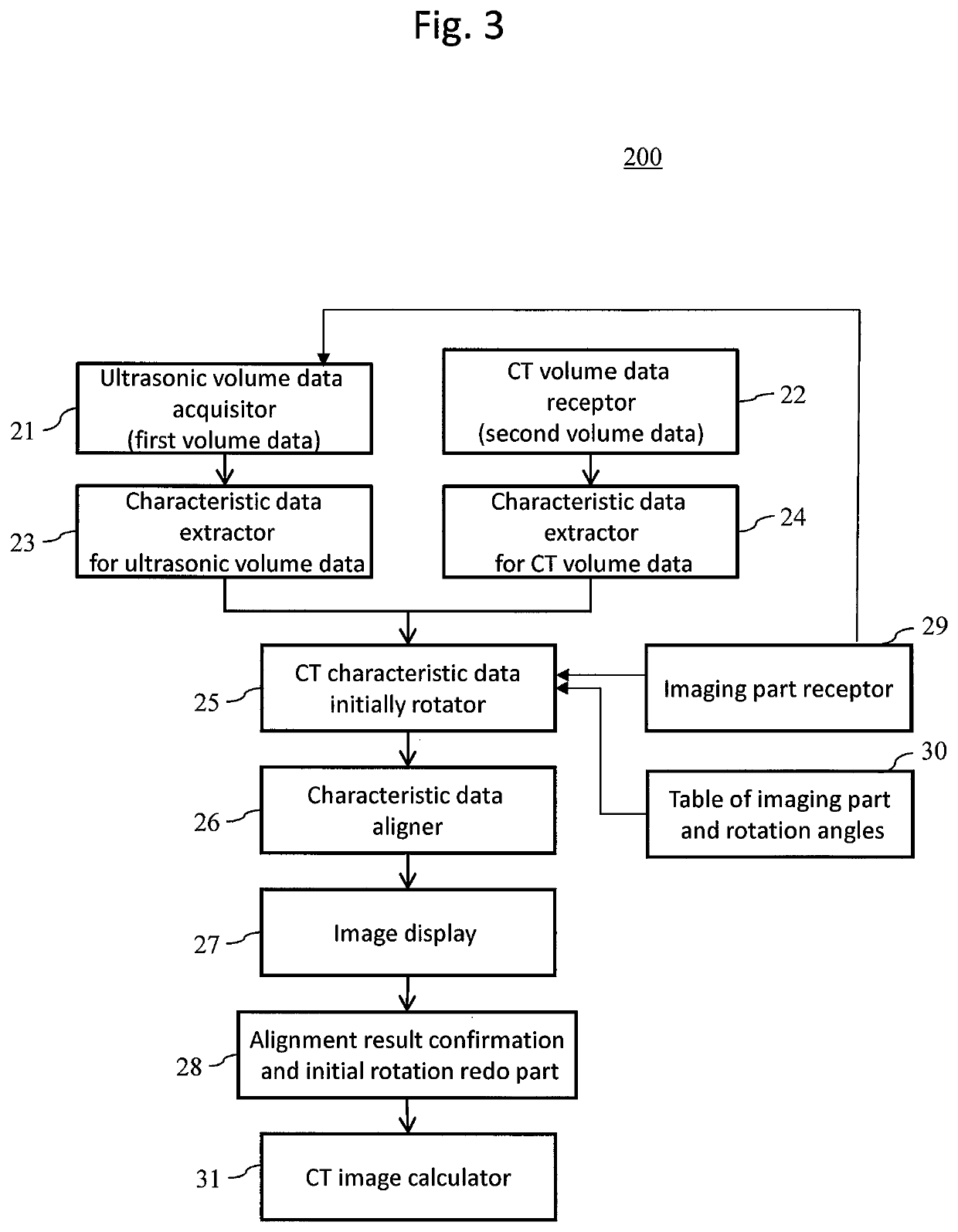
[0067]The ultrasonic imaging apparatus of the embodiment 2 does not comprises the table 30 shown in FIG. 5 in which a rotation angle is matched with each imaging part. As shown in the flowchart of FIG. 11, in the steps S201 to S204, the image processing device 108 extracts ultrasonic blood vessel data and CT blood vessel data in the same manner as that of the embodiment 1. Then, the angle for the initial rotation of the CT blood vessel data is obtained by calculation...
embodiment 3
[0072]The embodiment 3 will be explained below.
SUMMARY
[0073]In the embodiment 3, alignment accuracy is improved by further performing rigid body alignment for the ultrasonic volume data subjected to the alignment according to the embodiment 1 or 2, and aligned CT volume data.
[0074]The ultrasonic imaging apparatus of the embodiment 3 further comprises, in addition to the functional blocks shown in FIG. 3, an image-based rigid body aligner 300 shown in FIG. 12 in the image processing device 108. The image-based rigid body aligner 300 is a device for performing alignment of the aligned CT volume data obtained in the step S210 of the embodiment 1 shown in FIG. 6 or the step S210 of the embodiment 2 shown in FIG. 6 as a floating image 32, and ultrasonic volume data as a reference image 31.
[0075]The image-based rigid body aligner 300 comprises a characteristic region sampler 34 and an aligner 37.
[0076]FIG. 13 shows a flowchart for explaining the while operation of the rigid body aligner 3...
PUM
 Abstract
Description
Claims
Application Information
 - R&D
- Intellectual Property
- Life Sciences
- Materials
- Tech Scout
- Unparalleled Data Quality
- Higher Quality Content
- 60% Fewer Hallucinations
Browse by: Latest US Patents, China's latest patents, Technical Efficacy Thesaurus, Application Domain, Technology Topic, Popular Technical Reports.
© 2025 PatSnap. All rights reserved.Legal|Privacy policy|Modern Slavery Act Transparency Statement|Sitemap|About US| Contact US: help@patsnap.com


