Towing hook mounting structure

a technology for mounting structures and towing hooks, which is applied in the direction of towing devices, vehicle components, transportation and packaging, etc., to achieve the effects of enhancing the workability of mounting the towing hook, reducing the deformation of the frame, and improving the design of the mounting structur

Active Publication Date: 2021-09-14
TOYOTA JIDOSHA KK
View PDF12 Cites 0 Cited by
  • Summary
  • Abstract
  • Description
  • Claims
  • Application Information

AI Technical Summary

Benefits of technology

[0005]The present disclosure provides a towing hook mounting structure capable of suppressing local deformation of a frame regardless of a reinforcement.

Problems solved by technology

However, the towing hook mounting structure disclosed in JP 2008-189020 A has the following problems.

Method used


Image

  • Towing hook mounting structure
  • Towing hook mounting structure
  • Towing hook mounting structure

Examples


example 1

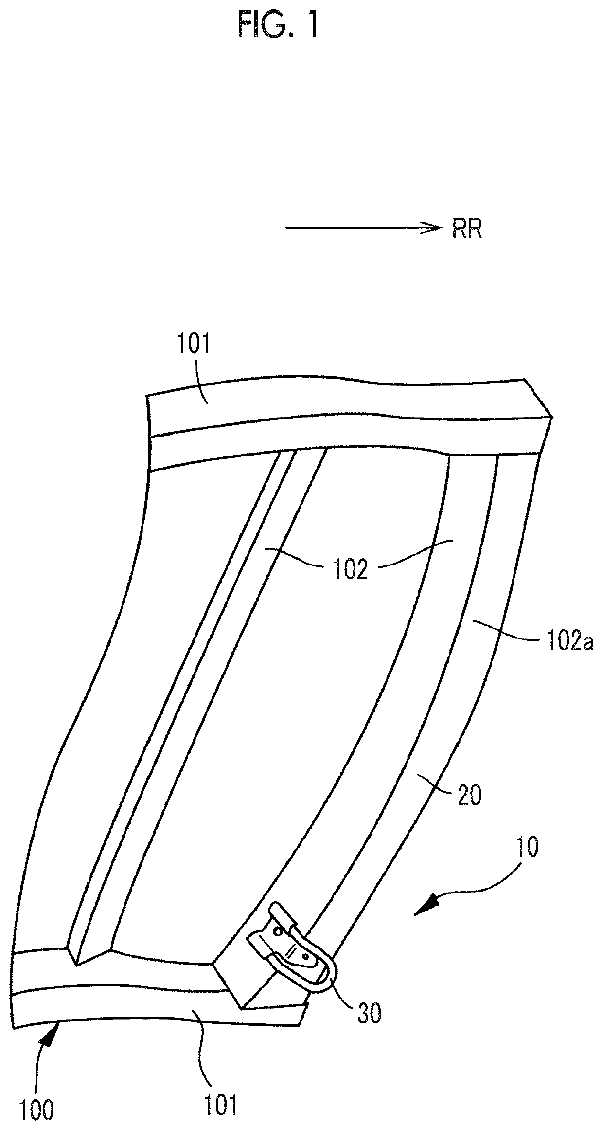
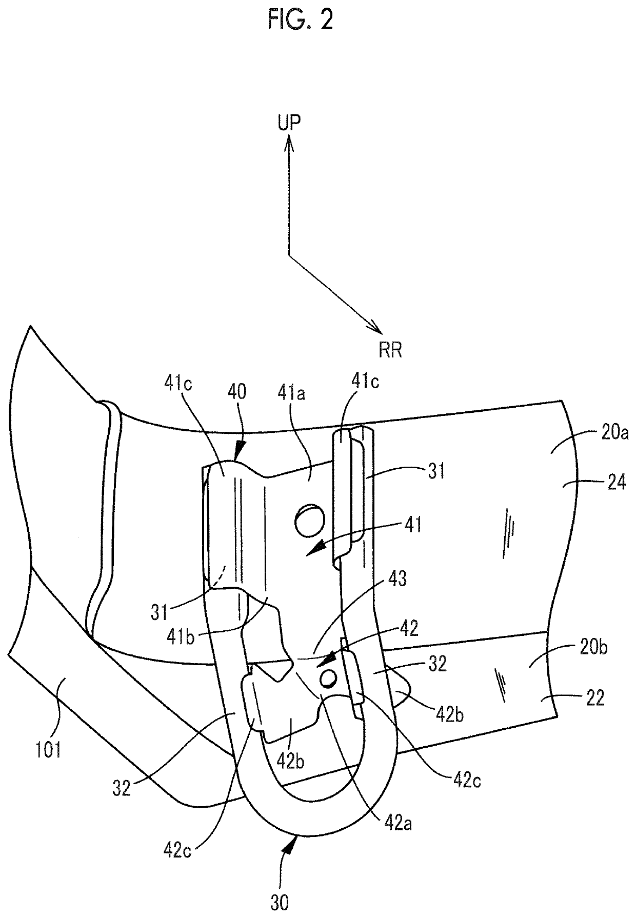
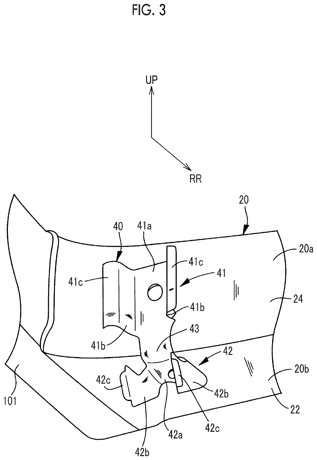
[0057]In Example 1 of the present disclosure, as shown in FIG. 2 and FIG. 3, the first hook portion 31 of the towing hook 30 is mounted to the first surface 20a of the frame 20 by using a first bracket 41 and the second hook portion 32 of the towing hook 30 is mounted to the second surface 20b of the frame 20 by using a second bracket 42.

[0058]The first bracket 41 is fabricated by pressing a metallic plate material. The first bracket 41 has a fixing portion 41a that is fixed to the first surface 20a of the frame 20 by welding or fastening using a bolt (not shown), an arm portion 41b extending from the fixing portion 41a toward the first hook portion 31 of the towing hook 30, and a hook retaining portion 41c that is provided at a tip portion in an extending direction of the arm portion 41b and welded and fixed to the first hook portion 31 of the towing hook 30 to retain the towing hook 30 at the first hook portion 31.

[0059]The second bracket 42 is fabricated by pressing a metallic pl...

example 2

[0064]In Example 2 of the present disclosure, as shown in FIG. 9, at least one of the mounting of the first hook portion 31 of the towing hook 30 to the first surface 20a and the mounting of the second hook portion 32 to the second surface 20b is directly performed by welding or bolting without using a bracket.

[0065]In FIG. 9, a case where the mounting of the first hook portion 31 to the first surface 20a is directly performed by bolting and the mounting of the second hook portion 32 to the second surface 20b is performed using a third bracket 44 is shown. The first hook portion 31 is directly fastened and fixed to the first surface 20a of the frame 20 after the first hook portion 31 is subjected to crushing processing and drilling processing.

[0066]In Example 2 of the present disclosure, the following unique effects can be obtained. At least one of the mounting of the first hook portion 31 to the first surface 20a and the mounting of the second hook portion 32 to the second surface ...


PUM


Abstract

A towing hook mounting structure includes a frame of a vehicle and a towing hook. The frame includes a first surface and a second surface having a planar direction different from that of the first surface. The towing hook includes a first hook portion and a second hook portion different from the first hook portion. The first hook portion of the towing hook is fixedly mounted to the first surface of the frame, and the second hook portion of the towing hook is fixedly mounted to the second surface of the frame.

Description

INCORPORATION BY REFERENCE[0001]The disclosure of Japanese Patent Application No. 2018-018884 filed on Feb. 6, 2018 including the specification, drawings and abstract is incorporated herein by reference in its entirety.BACKGROUND1. Technical Field[0002]The present disclosure relates to a towing hook mounting structure for mounting a towing hook to a frame of a vehicle.2. Description of Related Art[0003]Japanese Unexamined Patent Application Publication No. 2008-189020 (JP 2008-189020 A) discloses a technique of bolting a towing hook to solely a lower surface (one surface) of a frame of a vehicle through a bumper stay.[0004]However, the towing hook mounting structure disclosed in JP 2008-189020 A has the following problems. Since a towing hook is bolted to solely the lower surface (one surface) of the frame, the frame holds a load from the towing hook with mainly surface rigidity of the lower surface (one surface). For this reason, in a case where the towing hook is pulled downward d...

Claims


Application Information

Patent Timeline
Patent Type & Authority Patents(United States)
IPC IPC(8): B60D1/48
CPCB60D1/485B60D1/488
Inventor TAKAHASHI, HIDENOBUIKEYOSHI, MAIKOKIMURA, YUSUKEMARUISHI, YUICHIRO
Owner TOYOTA JIDOSHA KK
Why Eureka
Try Eureka