Conveyance roller for heating furnace

A heating furnace and conveying roller technology, which is applied in the field of suppressing deformation of conveying rollers, can solve problems such as obstacles in conveying objects to be heated, and achieve the effect of suppressing local deformation.

Inactive Publication Date: 2020-11-20
NORITAKE CO LTD
View PDF10 Cites 0 Cited by
  • Summary
  • Abstract
  • Description
  • Claims
  • Application Information

AI Technical Summary

Problems solved by technology

In this way, if the conveying roller used in the furnace is used for a long time, there is a problem that the outer peripheral surface of the conveying roller is continuously raised in a local deformation in the circumferential direction, and the transportation of the object to be heated is hindered.

Method used


Image

  • Conveyance roller for heating furnace
  • Conveyance roller for heating furnace
  • Conveyance roller for heating furnace

Examples


Embodiment 1

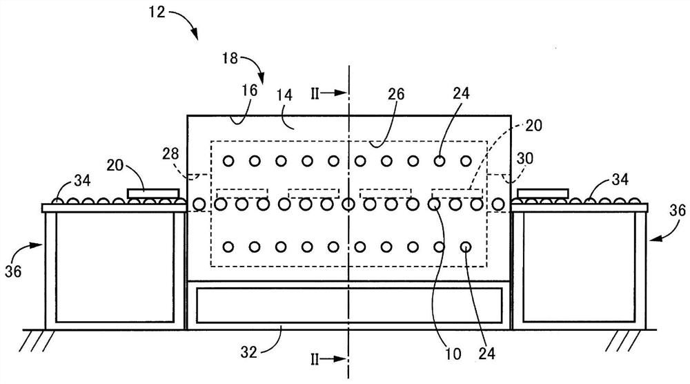
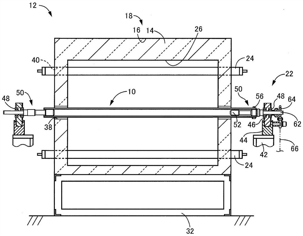
[0040] figure 1 It is a side view of a heating furnace provided with a conveying roller for a heating furnace (hereinafter referred to as conveying roller) 10 according to an embodiment of the present invention, for example, a batch conveying type steel plate heating furnace 12 . figure 2 yes figure 1 The II-II arrow sectional view of the intermittent conveying type steel plate heating furnace 12. The batch-transfer steel plate heating furnace 12 includes: a long furnace body 18 composed of a heat insulating material 14 for keeping the inside of the furnace at a high temperature and a casing 16 covering the heat insulating material 14; A plurality of conveying rollers 10 arranged in parallel at predetermined intervals to convey it from one end to the other end in the longitudinal direction of the furnace body 18; a conveying roller support device 22 rotatably supporting both ends of the conveying rollers 10; An unillustrated roller driving device that intermittently drives ...

Embodiment 2

[0060] Figure 9 represents the equivalent of the conveying roller 110 in another embodiment of the present invention Figure 5 diagram. exist Figure 5 In the above, the shielding member 72 is a short tube made of a heat-resistant alloy, but it may also be as Figure 9 Like the shielding member 172 shown, instead of short tubes made of a heat-resistant alloy, the height h of the supporting protrusions 70 from the outer peripheral surface of the roller main body 68 is made to cover the outer peripheral surface of the roller main body 68 between the supporting protrusions 70 or less. The thickness of the coiled insulation material. The heat insulating material is composed of, for example, a strip-shaped heat insulating material woven with heat insulating material fibers such as ceramic fibers such as fused silica and alumina.

[0061] According to the conveying roller 110 of the present embodiment, the shielding member 172 is preferably wound around the ring so as to cover ...

Embodiment 3

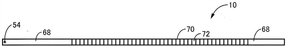
[0063] Figure 10 represents the equivalent of the main part of the conveying roller 210 in another embodiment of the present invention Figure 4 diagram. exist Figure 10 Among them, the supporting protrusion 270 is constituted by one helical wire made of a heat-resistant alloy welded to the outer peripheral surface of the roller main body 68 in a helical shape. In addition, in the longitudinal direction of the roller main body 68 , the shielding member 272 is attached to the spiral shape so as to cover the outer peripheral surface of the roller main body 68 with a thickness equal to or less than the height h of the supporting protrusion 270 from the outer peripheral surface of the roller main body 68 . The heat insulating material between the filaments is formed in a spiral tube shape. The shielding member 272 can be easily constructed by winding a tape-shaped heat insulating material woven of heat insulating material fibers such as ceramic fibers such as fused silica and...


PUM

PropertyMeasurementUnit
lengthaaaaaaaaaa

Abstract

Provided is a conveyance roller for a heating furnace, the roller being resistant to local deformation. A steel sheet is conveyed in a state held entirely by holding projections (70), which are made of a heat-resistant alloy and protrude higher than a shielding member (72), at multiple positions on the outer circumferential surface of a roller body (68) at a specified interval in the longitudinaldirection of the roller body (68). The holding projections (70) made of a heat-resistant alloy contact the inward-conveyed, cold steel sheet over little contact area, so the transmission of heat fromthe roller body (68) to the steel sheet is minimal, rapid cooling of the roller body (68) is suppressed due to radiative cooling from the hot roller body (68) being shielded by the shielding member (72) provided between the holding projections (70), and local deformation of the outer circumferential surface of the roller body (68) is suppressed. As a result, the holding projections (70) do not deform, and the occurrence of hindrances to the conveyance of the steel sheet is resolved.

Description

technical field [0001] The present invention relates to a conveying roller for a heating furnace that uses a conveying roller to take a cold object into a heating furnace and convey the heated object out of the heating furnace, and particularly relates to a technology for suppressing deformation of the conveying roller. Background technique [0002] Conventionally, as a heating furnace for heating objects such as steel sheets and sintered alloy molded objects to red heat, the objects to be heated at room temperature are transported into the furnace while supporting them, and the heated objects are transported into the furnace. As a member for transporting heated objects, a transport roller with high thermal shock resistance and thermal deformation resistance has been proposed, which has an elongated shape and has both ends in the state where the middle part in the longitudinal direction is located in the heating furnace. The heating furnace is supported outside. For example...

Claims


Application Information

Patent Timeline
Patent Type & Authority Applications(China)
IPC IPC(8): C21D1/00B65G39/07B65H5/06F27B9/24
CPCF27B9/24B65G39/07C21D1/00B65H5/066B65H2701/173F27B9/2407F27D3/026B65G39/02C21D9/563B65G2201/022B65H2301/44324B65H5/06
Inventor 植田洋俊铃木清孝神田武幸山本茂仁
Owner NORITAKE CO LTD
Why Eureka
Try Eureka